
In this tutorial we will demonstrate that how can you
- Configure Access or Trunk links
- Create VLAN
- Assign VLAN membership
- Configure Intra VLAN routing
- Configure VTP Server
- Make VTP Clients
- Show STP Static
- Configure DTP port
To complete these labs either creates a topology as shown in figure or downloads this file and loads it in packet tracer

Task
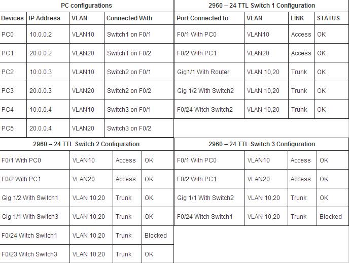
You are the administrator at router-switch.com have two department sales and management. You have given three pc for sales and three pc in management. You created two VLAN. VLAN 10 for sales and VLAN20 for management. For backup purpose you have interconnected switch with one extra connection. You have one router for intera VLAN communications.
Let’s start configuration first assign IP address to all pc’s
To assign IP address double click on pc and select ip configurations from desktop tab and give ip address as shown in table given above
VLAN Trunking Protocol
Configure VTP Server
We will first create a VTP Server so it can automatically propagate VLAN information to other switch. Double click on Switch1 and select CLI. Set hostname to S1 and create VTP domain name example and set password to vinita (Remember password is case sensitive).
Switch 1
Switch>enable
Switch#configure terminal
Enter configuration commands, one per line. End with CNTL/Z.
Switch(config)#hostname S1
S1(config)#vtp mode server
Device mode already VTP SERVER.
S1(config)#vtp domain example
Changing VTP domain name from NULL to example
S1(config)#vtp password vinita
Setting device VLAN database password to vinita
Configure VTP clients
Once you have created a VTP domain. Configure remaining Switch to Client mode.
Switch 2
Switch>enable
Switch#configure terminal
Enter configuration commands, one per line. End with CNTL/Z.
Switch(config)#hostname S2
S2(config)#vtp mode client
Setting device to VTP CLIENT mode.
S2(config)#vtp domain example
Changing VTP domain name from NULL to example
S2(config)#vtp password vinita
Setting device VLAN database password to vinita
S2(config)#
Switch 3
Switch>enable
Switch#configure terminal
Enter configuration commands, one per line. End with CNTL/Z.
Switch(config)#hostname S3
S3(config)#vtp mode client
Setting device to VTP CLIENT mode.
S3(config)#vtp domain example
Changing VTP domain name from NULL to example
S3(config)#vtp password vinita
Setting device VLAN database password to vinita
S3(config)#
Dynamic Trunking Protocol
Configure DTP port
All Switch ports remain by default in access mode. Access port can not transfer the trunk frame. Change mode to trunk on all the port those are used to interconnect the switches
Switch 1
S1(config)#interface fastEthernet 0/24
S1(config-if)#switchport mode trunk
%LINEPROTO-5-UPDOWN: Line protocol on Interface FastEthernet0/24,
changed state to down
%LINEPROTO-5-UPDOWN: Line protocol on Interface FastEthernet0/24,
changed state to up
S1(config-if)#exit
S1(config)#interface gigabitEthernet 1/1
S1(config-if)#switchport mode trunk
S1(config-if)#exit
S1(config)#interface gigabitEthernet 1/2
S1(config-if)#switchport mode trunk
%LINEPROTO-5-UPDOWN: Line protocol on Interface GigabitEthernet1/2,
changed state to down
%LINEPROTO-5-UPDOWN: Line protocol on Interface GigabitEthernet1/2,
changed state to up
S1(config-if)#exit
S1(config)#
Switch 2
S2(config)#interface gigabitEthernet 1/1
S2(config-if)#switchport mode trunk
%LINEPROTO-5-UPDOWN: Line protocol on Interface GigabitEthernet1/1,
changed state to down
%LINEPROTO-5-UPDOWN: Line protocol on Interface GigabitEthernet1/1,
changed state to up
S2(config-if)#exit
S2(config)#interface gigabitEthernet 1/2
S2(config-if)#switchport mode trunk
S2(config-if)#exit
S2(config)#interface fastEthernet 0/23
S2(config-if)#switchport mode trunk
%LINEPROTO-5-UPDOWN: Line protocol on Interface FastEthernet0/23,
changed state to down
%LINEPROTO-5-UPDOWN: Line protocol on Interface FastEthernet0/23,
changed state to up
S2(config-if)#exit
S2(config)#interface fastEthernet 0/24
S2(config-if)#switchport mode trunk
S2(config-if)#exit
Switch 3
S3(config)#interface fastEthernet 0/24
S3(config-if)#switchport mode trunk
S3(config-if)#exit
S3(config)#interface gigabitEthernet 1/1
S3(config-if)#switchport mode trunk
S3(config-if)#exit
Virtual LAN (VLAN)
Create VLAN
After VTP server configuration it’s time to organize VLAN. We need only to create VLAN on VTP server and reset will be done by VTP Server automatically.
Switch 1
S1(config)#vlan 10
S1(config-vlan)#exit
S1(config)#vlan 20
S1(config-vlan)#exit
S1(config)#
As we have already configured VTP server in our network so we don’t need to create VLAN on S2 or S3. We need only to associate VLAN with port.
Assign VLAN membership
Switch 1
S1(config)#interface fastEthernet 0/1
S1(config-if)#switchport access vlan 10
S1(config-if)#interface fastEthernet 0/2
S1(config-if)#switchport access vlan 20
Switch 2
S2(config)#interface fastEthernet 0/1
S2(config-if)#switchport access vlan 10
S2(config-if)#interface fastEthernet 0/2
S2(config-if)#switchport access vlan 20
Switch 3
S3(config)#interface fastEthernet 0/1
S3(config-if)#switchport access vlan 10
S3(config-if)#interface fastEthernet 0/2
S3(config-if)#switchport access vlan 20
Now we have two working vlan. To test connectivity do ping form 10.0.0.2 to 10.0.0.3 and 10.0.0.4. if you get successfully replay then you have successfully created VLAN and VTP server.
Spanning-Tree Protocol
In this configuration STP will block these ports F0/24 of S1 , F0/23 and F0/24 of S2 and F0/24 of S3 to avoid loop at layer to two. Verify those ports blocked due to STP functions
Verify STP ports
Switch 2
S2#show spanning-tree active
VLAN0001
Spanning tree enabled protocol ieee
Root ID Priority 32769
Address 0002.174D.7794
Cost 4
Port 26(GigabitEthernet1/2)
Hello Time 2 sec Max Age 20 sec Forward Delay 15 sec
Bridge ID Priority 32769 (priority 32768 sys-id-ext 1)
Address 00D0.FF08.82E1
Hello Time 2 sec Max Age 20 sec Forward Delay 15 sec
Aging Time 20
Interface Role Sts Cost Prio.Nbr Type
—————- —- — ——— ——– —————————
Fa0/1 Desg FWD 19 128.1 P2p
Fa0/2 Desg FWD 19 128.2 P2p
Fa0/23 Desg FWD 19 128.23 P2p
Fa0/24 Altn BLK 19 128.24 P2p
Gi1/1 Desg FWD 4 128.25 P2p
Gi1/2 Root FWD 4 128.26 P2p
[Output is omitted]
S2#
You can test STP protocols status on S1 and S3 also with
show spanning-tree active command
Router on Stick
At this point of configuration you have two successfully running VLAN but they will not connect each other. To make intra VLAN communications we need to configure router . To do this double click on router and select CLI.
Configure intra VLAN
Router
Router>enable
Router#configure terminal
Enter configuration commands, one per line. End with CNTL/Z.
Router(config)#interface fastEthernet 0/0
Router(config-if)#no ip address
Router(config-if)#no shutdown
Router(config-if)#exit
Router(config)#interface fastEthernet 0/0.10
Router(config-subif)#encapsulation dot1Q 10
Router(config-subif)#ip address 10.0.0.1 255.0.0.0
Router(config-subif)#exit
Router(config)#interface fastEthernet 0/0.20
Router(config-subif)#encapsulation dot1Q 20
Router(config-subif)#ip address 20.0.0.1 255.0.0.0
Router(config-subif)#exit
To test connectivity between different vlan do ping form any pc to all reaming pc. it should be ping successfully. If you have error download this configured topology and cross check that where you have committed mistake.
Configured VLAN VTP STP topology
VLAN VTP Server STP DTP command reference sheet
| Switch(config)#vlan 10 | Creates VLAN 10 and enters VLAN configuration mode for further definitions. |
| Switch(config-vlan)#name Sales | Assigns a name to the VLAN. The length of the name can be from 1 to 32 characters. |
| Switch(config-vlan)#exit | Applies changes, increases the revision number by 1, and returns to global configuration mode. |
| Switch(config)#interface fastethernet 0/1 | Moves to interface configuration mode |
| Switch(config-if)#switchport mode access | Sets the port to access mode |
| Switch(config-if)#switchport access vlan 10 | Assigns this port to VLAN 10 |
| Switch#show vlan | Displays VLAN information |
| Switch#show vlan brief | Displays VLAN information in brief |
| Switch#show vlan id 10 | Displays information about VLAN 10 only |
| Switch#show vlan name sales | Displays information about VLAN named sales only |
| Switch#show interfaces vlan x | Displays interface characteristics for the specified VLAN |
| Switch#delete flash:vlan.dat Delete filename [vlan.dat]? Delete flash:vlan.dat? [confirm] Switch# |
Removes the entire VLAN database from flash. Make sure there is no space between the colon (:) and the characters vlan.dat. You can potentially erase the entire contents of the flash with this command if the syntax is not correct. Make sure you read the output from the switch. If you need to cancel, press ctrl+c to escape back to privileged mode: |
| Switch(config)#interface fastethernet 0/5 | Moves to interface configuration mode. |
| Switch(config-if)#no switchport access vlan 5 | Removes port from VLAN 5 and reassigns it to VLAN 1—the default VLAN. |
| Switch(config-if)#exit | Moves to global configuration mode. |
| Switch(config)#no vlan 5 | Removes VLAN 5 from the VLAN database. |
| Switch#copy running-config startupconfig | Saves the configuration in NVRAM |
| Switch(config-if) #switchport mode trunk | Puts the interface into permanent trunking mode and negotiates to convert the link into a trunk link. |
| Switch(config)#vtp mode server | Changes the switch to VTP server mode. |
| Switch(config)#vtp mode client | Changes the switch to VTP client mode. |
| Switch(config)#vtp mode transparent | Changes the switch to VTP transparent mode. |
| Switch(config)#no vtp mode | Returns the switch to the default VTP server mode. |
| Switch(config)#vtp domain domain-name | Configures the VTP domain name. The name can be from 1 to 32 characters long. |
| Switch(config)#vtp password password | Configures a VTP password
. |
| Switch(config)#vtp pruning | Enables VTP pruning |
| Switch#show vtp status | Displays general information about VTP configuration |
| Switch#show vtp counters | Displays the VTP counters for the switch |
Guide from ComputerNetworkingNotes.com
More Related Topics:
Video to Show Private VLANs & Configure PVLANs on A Cisco Switch
How to Configure Spanning Tree Protocol (STP) on Catalyst Switches?
How the Root Bridge and Ports are Chosen?