
In this article we will discuss how to establish communications between VLANs, as well as how to configure the networks.
Notes: More about the virtual LANs, Physical LANs and briefly reviewed VLAN configuration options you can read the articles shared here:
Virtual vs. Physical LANs: Device Functionalities and VLAN Configuration Fundamentals and Commands
First of all, let’s take a look at the 3 methods of permitting traffic to flow between VLANs
Communications Options:
- Configure a router and connect a single interface to a switch per VLAN configured.
- Configure a router to use IEEE 802.1Q and connect to a switch via a trunk.
- Configure (and possibly purchase) a Layer 3–capable switch.
Option 1 is really only practical for companies that are very small, don’t require a large number of ports, and don’t anticipate growing quickly. This option’s only opportunity for growth is by using an expensive router port (per VLAN). Options 2 and 3 are appropriate for the majority of networks deployed over the last 15 years or so.
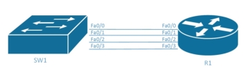
This example assumes that four different VLANs on SW1 need to be connected together. Using this option, a new interface is required per device per VLAN, all of which need to communicate, so four different interfaces are linked from the Layer 2 switch (SW1) to the router (R1). If the company wants to add another VLAN sometime in the future, it will need a new interface to link the new VLAN from SW1 to R1. This network design is inherently wasteful because many VLANs don’t have a lot of traffic passing between devices. (That’s the point of having the VLAN in the first place.) The ineffective design of option 1 explains why option 2 started getting attention.
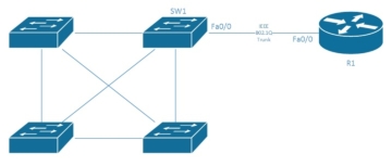
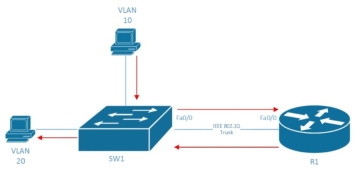
Option 2 is popular with companies that need to connect multiple VLANs, but can’t afford Layer 3 switching options. When implementing this design, an 802.1Q trunk is configured between a Layer 2 switch and a router that supports 802.1Q. This trunk allows all of the traffic from the configured VLANs to be transmitted and routed via a single routed interface. The router manages and routes all traffic from one VLAN to another via this single interface. This type of configuration is typically referred to as router on a stick (ROAS). The following figure shows a common representation of this configuration.
All VLANs over a single interface
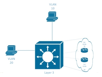
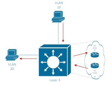
The third option for routing traffic between VLANs is to use a Layer 3 switch. This switch is capable of routing traffic from VLAN to VLAN internally, but it tends to be quite a bit more expensive than a Layer 2 switch. Older-model switches performed this routing via a separate routing blade that was inserted into the switch, but on modern switches this functionality is typically built into the switch. Cisco IOS switches handle this functionality via the use of a switch virtual interface (SVI). It shows a visual representation of the SVIs inside a Layer 3 switch as follows.
All VLANs internal to the Layer 3 switch
The Forwarding Path
Here’s the next logical question: How is traffic forwarded between VLANs? For the answer, we’ll take a look at all three connectivity models discussed earlier.
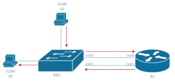
For option 1, let’s assume that two devices need to communicate—one is configured into VLAN 10, and the other is configured into VLAN 20. We’ll also assume that the Fa0/0 interface communicates with VLAN 10 traffic and the Fa0/1 interface communicates with VLAN 20 traffic. In this scenario, traffic from the VLAN 10 device will flow to the VLAN 20 device using the path shown in the following figure.
Now let’s condense this layout a little and look at how the forwarding would work with a ROAS configuration. The Figure below, notice that the path looks very similar, but without needing an extra interface.
Finally, let’s look at how this design works with a Layer 3 switch. This layout is a bit different because it doesn’t need a separate routing device. In this case, the routing mechanism is built into the same switch, and SVIs route the traffic.
Network Configuration
Configuring any of the network options requires a good understanding of the concepts laid out in the previous sections. All of the following examples use four different VLANs: VLAN 10, VLAN 20, VLAN 30, and VLAN 40.
The option 1 configuration requires the interfaces connected to the router to be configured into the correct VLANs. No special configuration is required on R1, as each interface would be configured like a standard LAN interface; the VLANs are invisible to R1 in this configuration.
Table 1 shows an example, using the diagram from the figure 1.
| Step | Action(s) | Command(s) |
| 1 | Enter global configuration mode. | SW1#configure terminal |
| 2 | Enter into VLAN configuration mode and/or create a VLAN (optional). | SW1(config)#vlan vlan-id |
| 3 | Configure a name for the VLAN (optional). | SW1(config-vlan)#namename |
| 4 | Enter into interface configuration mode for the first interface connecting to R1. | SW1(config-vlan)#interface fastethernet0/0 |
| 5 | Configure the access VLAN for the interface. | SW1(config-if)#switchport access vlan 10 |
| 6 | Enter into interface configuration mode for the second interface connecting to R1. | SW1(config-vlan)#interface fastethernet0/1 |
| 7 | Configure the access VLAN for the interface. | SW1(config-if)#switchport access vlan 20 |
| 8 | Enter into interface configuration mode for the third interface connecting to R1. | SW1(config-vlan)#interface fastethernet0/2 |
| 9 | Configure the access VLAN for the interface. | SW1(config-if)#switchport access vlan 30 |
| 10 | Enter into interface configuration mode for the fourth interface connecting to R1. | SW1(config-vlan)#interface fastethernet0/3 |
| 11 | Configure the access VLAN for the interface. | SW1(config-if)#switchport access vlan 40 |
For option 2, the router must become aware of the VLANs being used and route accordingly.
Table 2 shows an example of this configuration, using the diagram from “All VLANs over a single interface”.
| Step | Action(s) | Command(s) |
| 1 | Enter global configuration mode. | SW1#configure terminal |
| 2 | Enter into VLAN configuration mode and/or create a VLAN (optional). | SW1(config)#vlan vlan-id |
| 3 | Configure a name for the VLAN (optional). | SW1(config-vlan)#namename |
| 4 | Enter into interface configuration mode for the first interface connecting to R1. | SW1(config-vlan)#interface fastethernet0/0 |
| 5 | Configure the interface to become a trunk.
Note: Routers don’t support the dynamic trunking protocol (DTP), so the trunk must be manually enabled. |
SW1(config-if)#switchport mode trunk |
| 6 | Enter global configuration mode. | R1#configure terminal |
| 7 | Create a new sub-interface on the physical interface connecting to SW1.
Note: For this example, I’m using sub-interface numbers that match the VLAN numbers, but this is not required. |
R1(config)#interface fastethernet0/0.10 |
| 8 | Configure the interface to use IEEE 802.1Q encapsulation and handle traffic for VLAN 10. | R1(config-if)#encapsulation dot1Q 10 |
| 9 | Create another new sub-interface on the physical interface connecting to SW1. | R1(config)#interface fastethernet0/0.20 |
| 10 | Configure the interface to use IEEE 802.1Q encapsulation and handle traffic for VLAN 20. | R1(config-if)#encapsulation dot1Q 20 |
| 11 | Create another new sub-interface on the physical interface connecting to SW1. | R1(config)#interface fastethernet0/0.30 |
| 12 | Configure the interface to use IEEE 802.1Q encapsulation and handle traffic for VLAN 30. | R1(config-if)#encapsulation dot1Q 30 |
| 8 | Create another new sub-interface on the physical interface connecting to SW1. | R1(config)#interface fastethernet0/0.40 |
| 9 | Configure the interface to use IEEE 802.1Q encapsulation and handle traffic for VLAN 40. | R1(config-if)#encapsulation dot1Q 40 |
All Layer 3 addressing information would now be configured on the sub-interfaces that are configured.
For option 3, the configuration requires that you set up the SVI within the switch to handle the VLAN traffic.
Table 3 shows an example of this configuration, using the diagram from “All VLANs internal to the Layer 3 switch”.
| Step | Action(s) | Command(s) |
| 1 | Enter global configuration mode. | SW1#configure terminal |
| 2 | Enter into VLAN configuration mode and/or create a VLAN (optional). | SW1(config)#vlan vlan-id |
| 3 | Configure a name for the VLAN (optional). | SW1(config-vlan)#namename |
| 4 | Configure a new SVI interface for the first VLAN (10). | SW1(config-vlan)#interface vlan 10 |
| 5 | Configure a new SVI interface for the second VLAN (20). | SW1(config-vlan)#interface vlan 20 |
| 6 | Configure a new SVI interface for the third VLAN (30). | SW1(config-vlan)#interface vlan 30 |
| 7 | Configure a new SVI interface for the fourth VLAN (40). | SW1(config-vlan)#interface vlan 40 |
All Layer 3 addressing information would now be configured on the SVI interfaces that are configured.
Today, the only solution that will be common in medium to large implementations is the use of Layer 3 switches. The other two solutions had their time, but as the technology and industry have evolved, the third solution has grown to be an easier (and overall cheaper) solution than its predecessors.
The use of VLANs on modern networks has continued to evolve and grow. A good knowledge of their purpose and how they are typically configured into an overall networking architecture is very important.
The original guide info shared by Sean Wilkins at https://www.ciscopress.com/articles/article.asp?p=2359568&seqNum=2
…More original articles written by Sean Wilkins you can read here https://www.ciscopress.com/authors/bio/e951adf7-0a98-4d8f-8e26-8b39eb63587d
More Related…