
It’s simple to explain What Private VLAN is, but Cisco’s implemenation and configuration steps are a bit confusing – with all the “mappings” and “associations” stuff. Here we will talk about Private VLAN and how private VLANs work.
Firstly, let’s check the concept of VLAN as a broadcast domain. What Private VLANs (PVANs) do, is split the domain into multiple isolated broadcast subdomains. It’s a simple nesting concept – VLANs inside a VLAN.
As we know, Ethernet VLANs are not allowed to communicate directly; they need L3 device to forward packets between broadcast domains. The same concept applies to PVLANS – since the subdomains are isolated at level 2, they need to communicate using an upper level (L3 and packet forwarding) entity – such as router. However, there is difference here.
Regular VLANs usually correspond to a single IP subnet. When we split VLAN using PVLANs, hosts in different PVLANs still belong to the same IP subnet, but they need to use router (another L3 device) to talk to each other (for example, by means of local Proxy ARP). In turn, router may either permit or forbid communications between sub-VLANs using access-lists.
Why would anyone need Private VLANs? Commonly, this kind of configurations arise in “shared” environments, say ISP co-location, where it’s beneficial to put multiple customers into the same IP subnet, yet provide a good level of isolation between them.
Private VLAN and Its Function

For our sample configuration, we take VLAN 1000 and divide it into three PVLANs – sub-VLAN 1012 (R1 and R2), sub-VLAN 1034 (R3 and R4) and sub-VLAN 1055 (router R5 only). Router R6 will be used as layer 3 device, to resolve the layer 3 communication issue. We name VLAN 1000 as “Primary” and classify the ports, assigned to this VLAN, based on their types:
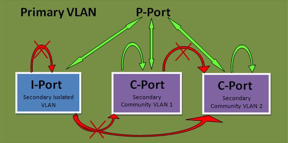
Promiscuous (“P”) port: Usually connects to a router. This port type is allowed to send and receive L2 frames from any other port on the VLAN.
Isolated (“I”) port: This type of port is only allowed to communicate with “P”-ports – i.e., they are “stub” port. You commonly see these ports connecting to hosts.
Community (“C”) port: Community ports are allowed to talk to their buddies, sharing the same community (group) and to “P”-ports.
In order to implement sub-VLAN behavior, we need to define how packets are forwarded between different types of ports. We group the VLANs in “Primary” and “Secondary”.
Primary VLAN (VLAN 1000 in our example). This VLAN is used to forward frames downstream from “P”-ports to all other port types (“I” and “C” ports) in the system. Essentially, Primary VLAN embraces all ports in the domain, but only transports frames from the router to hosts (from “P” to “I” and “C”).
Secondary Isolated VLAN: forwards frames from “I” ports to “P” ports. Since Isolated ports do not exchange frames with each other, we can use just ONE isolated VLAN to connect all I-Port to the P-port.
Secondary Community VLANs: Transport frames between community ports (C-ports) within to the same group (community) and forward frames upstream to the P-ports of the primary VLAN.
How Private VLANs Work
Here are the key aspects of Private VLAN functioning:
- The Primary VLAN delivers frames downstream from the router (promisc port) to all mapped hosts.
- The Isolated VLAN transports frames from the stub hosts upstream to the router
- The Community VLANs allow bi-directional frame exchange within a single group, in addition to forwarding frames upstream towards “P”-ports.
- Ethernet MAC address learning and forwarding procedure remain the same, as well as broadcast/multicast flooding procedure within boundaries of primary/secondary VLANs.
Private VLANs could be trunked. The secondary VLAN numbers are used to tag frames, just as with regular VLANs, and the primary VLAN traffic is trunked as well. However, you need to configure Private VLAN specific settings (bindings, mappings) on every participating switch, as it’s not possible to use VTPv2 to disseminate that information. This due to the fact that VTPv2 has no TLVs to carry private VLANs information. VTPv3 was designed to overcome this limitation among others.
Configuring Private VLANs
We have primary VLAN 1000, Isolated VLAN 1005 (R5) Community VLAN 1012 (R1, R2) and Community VLAN 1034 (R3, R4).
Step 1: First, disable VTP, i.e. enable VTP transparent mode. After disabling VTP, create Primary and Secondary VLANs and bind them into PVLAN domain:
SW1:
vtp mode transparent
!
! Creating primary VLAN, which is shared among secondary’s
!
vlan 1000
private-vlan primary
!
! Community VLAN for R1 and R2: allows a “subVLAN” within a Primary VLAN
!
vlan 1012
private-vlan community
!
! Community VLAN for R3 and R4
!
vlan 1034
private-vlan community
!
! Isolated VLAN: Connects all stub hosts to router.
! Remember – only one isolated vlan per primary VLAN.
! In our case, isolates R5 only.
!
vlan 1055
private-vlan isolated
!
! Associating the primary with secondary’s
!
vlan 1000
private-vlan association 1012,1034,1055
This step is needed is to group PVLANs into a shared domain and establish a formal association (for syntax checking and VLAN type verifications). Repeat the same operations on SW2, since VTP has been disabled.
Step 2: Configure host ports and bind them to the respective isolated PVLANs. Note that a host port belongs to different VLANs at the same time: downstream primary and upstream secondary. Also, enable trunking between switches, to allow private VLANs traffic to pass between switches.
SW1:
!
! Community port (links R1 to R2 and “P”-ports)
!
interface FastEthernet0/1
description == R1
switchport private-vlan host-association 1000 1012
switchport mode private-vlan host
spanning-tree portfast
!
! Community port (links R3 to R4 and “P”-ports)
!
interface FastEthernet0/3
description == R3
switchport private-vlan host-association 1000 1034
switchport mode private-vlan host
spanning-tree portfast
!
! Isolated port (uses isolated VLAN to talk to “P”-ports)
!
interface FastEthernet0/5
description == R5
switchport private-vlan host-association 1000 1055
switchport mode private-vlan host
spanning-tree portfast
!
! Trunk port
!
interface FastEthernet 0/13
switchport trunk encapsulation dot1q
switchport mode trunk
SW2:
interface FastEthernet0/2
description == R2
switchport private-vlan host-association 1000 1012
switchport mode private-vlan host
spanning-tree portfast
!
interface FastEthernet0/4
description == R4
switchport private-vlan host-association 1000 1034
switchport mode private-vlan host
spanning-tree portfast
!
! Trunk port
!
interface FastEthernet 0/13
switchport trunk encapsulation dot1q
switchport mode trunk
Next, Verify the configuration on SW1:
Rack1SW1#show vlan id 1012
VLAN Name Status Ports
—- ——————————– ——— ——————————-
1012 VLAN1012 active Fa0/13
VLAN Type SAID MTU Parent RingNo BridgeNo Stp BrdgMode Trans1 Trans2
—- —– ———- —– —— —— ——– —- ——– —— ——
1012 enet 101012 1500 – – – – – 0 0
Remote SPAN VLAN
—————-
Disabled
Primary Secondary Type Ports
——- ——— —————– ——————————————
1000 1012 community Fa0/1
Rack1SW1#show vlan id 1034
VLAN Name Status Ports
—- ——————————– ——— ——————————-
1034 VLAN1034 active Fa0/13
VLAN Type SAID MTU Parent RingNo BridgeNo Stp BrdgMode Trans1 Trans2
—- —– ———- —– —— —— ——– —- ——– —— ——
1034 enet 101034 1500 – – – – – 0 0
Remote SPAN VLAN
—————-
Disabled
Primary Secondary Type Ports
——- ——— —————– ——————————————
1000 1034 community Fa0/3
Rack1SW1#show vlan id 1055
VLAN Name Status Ports
—- ——————————– ——— ——————————-
1055 VLAN1055 active Fa0/13
VLAN Type SAID MTU Parent RingNo BridgeNo Stp BrdgMode Trans1 Trans2
—- —– ———- —– —— —— ——– —- ——– —— ——
1055 enet 101055 1500 – – – – – 0 0
Remote SPAN VLAN
—————-
Disabled
Primary Secondary Type Ports
——- ——— —————– ——————————————
1000 1055 isolated Fa0/5
Rack1SW1#show interfaces fastEthernet 0/13 trunk
Port Mode Encapsulation Status Native vlan
Fa0/13 desirable 802.1q trunking 1
Port Vlans allowed on trunk
Fa0/13 1-4094
Port Vlans allowed and active in management domain
Fa0/13 1,1000,1012,1034,1055
Port Vlans in spanning tree forwarding state and not pruned
Fa0/13 1,1000,1012,1034,1055
Verify on SW2:
Rack1SW2#show vlan id 1000
VLAN Name Status Ports
—- ——————————– ——— ——————————-
1000 VLAN1000 active Fa0/13
VLAN Type SAID MTU Parent RingNo BridgeNo Stp BrdgMode Trans1 Trans2
—- —– ———- —– —— —— ——– —- ——– —— ——
1000 enet 101000 1500 – – – – – 0 0
Remote SPAN VLAN
—————-
Disabled
Primary Secondary Type Ports
——- ——— —————– ——————————————
1000 1012 community Fa0/2, Fa0/6
1000 1034 community Fa0/4, Fa0/6
1000 1055 isolated Fa0/6
Rack1SW2#show vlan id 1012
VLAN Name Status Ports
—- ——————————– ——— ——————————-
1012 VLAN1012 active Fa0/13
VLAN Type SAID MTU Parent RingNo BridgeNo Stp BrdgMode Trans1 Trans2
—- —– ———- —– —— —— ——– —- ——– —— ——
1012 enet 101012 1500 – – – – – 0 0
Remote SPAN VLAN
—————-
Disabled
Primary Secondary Type Ports
——- ——— —————– ——————————————
1000 1012 community Fa0/2, Fa0/6
Rack1SW2#show vlan id 1034
VLAN Name Status Ports
—- ——————————– ——— ——————————-
1034 VLAN1034 active Fa0/13
VLAN Type SAID MTU Parent RingNo BridgeNo Stp BrdgMode Trans1 Trans2
—- —– ———- —– —— —— ——– —- ——– —— ——
1034 enet 101034 1500 – – – – – 0 0
Remote SPAN VLAN
—————-
Disabled
Primary Secondary Type Ports
——- ——— —————– ——————————————
1000 1034 community Fa0/4, Fa0/6
Rack1SW2#show vlan id 1055
VLAN Name Status Ports
—- ——————————– ——— ——————————-
1055 VLAN1055 active Fa0/13
VLAN Type SAID MTU Parent RingNo BridgeNo Stp BrdgMode Trans1 Trans2
—- —– ———- —– —— —— ——– —- ——– —— ——
1055 enet 101055 1500 – – – – – 0 0
Remote SPAN VLAN
—————-
Disabled
Primary Secondary Type Ports
——- ——— —————– ——————————————
1000 1055 isolated Fa0/6
Rack1SW2#show interface fastEthernet 0/13 trunk
Port Mode Encapsulation Status Native vlan
Fa0/13 desirable 802.1q trunking 1
Port Vlans allowed on trunk
Fa0/13 1-4094
Port Vlans allowed and active in management domain
Fa0/13 1,1000,1012,1034,1055
Port Vlans in spanning tree forwarding state and not pruned
Fa0/13 1,1000,1012,1034,1055
Step 3: Create a promiscuous port and configure downstream mappings. Here we add secondary VLANs for which traffic is received by this particular “P”-port. Primary VLAN is used to send traffic downstream to all “C” and “I” ports per their associations.
SW2:
!
! Promiscuous port, mapped to all secondary VLANs
!
interface FastEthernet0/6
description == R6
switchport private-vlan mapping 1000 1012,1034,1055
switchport mode private-vlan promiscuous
spanning-tree portfast
Verify the promiscuous port configuration:
Rack1SW2#show int fa 0/6 switch | beg private
Administrative Mode: private-vlan promiscuous
Operational Mode: private-vlan promiscuous
Administrative Trunking Encapsulation: negotiate
Operational Trunking Encapsulation: native
Negotiation of Trunking: Off
Access Mode VLAN: 1 (default)
Trunking Native Mode VLAN: 1 (default)
Administrative Native VLAN tagging: enabled
Voice VLAN: none
Administrative private-vlan host-association: none
Administrative private-vlan mapping: 1000 (VLAN1000) 1012 (VLAN1012) 1034 (VLAN1034) 1055 (VLAN1055)
Administrative private-vlan trunk native VLAN: none
Administrative private-vlan trunk Native VLAN tagging: enabled
Administrative private-vlan trunk encapsulation: dot1q
Administrative private-vlan trunk normal VLANs: none
Administrative private-vlan trunk private VLANs: none
Operational private-vlan:
1000 (VLAN1000) 1012 (VLAN1012) 1034 (VLAN1034) 1055 (VLAN1055)
If you need to configure an SVI on a switch to communicate with private VLAN members, you should add an interface corresponding to Primary VLAN only. Obviously that’s because all secondary VLANs are “subordinates” of primary. After an SVI has been created, you have to map the required secondary VLANs to the SVI (just like with a promiscuous port) in order to make communications possible. You may exclude some mappings from SVI interface, and limit it to communicating only with certain secondary VLANs.
SW1:
!
! SW1 SVI is mapped to all secondary VLANs
!
interface Vlan 1000
ip address 10.0.0.7 255.255.255.0
private-vlan mapping 1012,1034,1055
SW2:
!
! SW2 SVI is mapped to 1012/1034 only, so it’s cant communicate with R5
!
interface Vlan1000
ip address 10.0.0.8 255.255.255.0
private-vlan mapping 1012,1034
Now to verify the configuration, configure R1-R6 interfaces in subnet “10.0.0.0/24” and ping broadcast addresses.
Rack1R1#ping 10.0.0.255 repeat 1
Type escape sequence to abort.
Sending 1, 100-byte ICMP Echos to 10.0.0.255, timeout is 2 seconds:
Reply to request 0 from 10.0.0.7, 4 ms
Reply to request 0 from 10.0.0.2, 4 ms
Reply to request 0 from 10.0.0.6, 4 ms
Reply to request 0 from 10.0.0.8, 4 ms
Rack1R3#ping 10.0.0.255 repeat 1
Type escape sequence to abort.
Sending 1, 100-byte ICMP Echos to 10.0.0.255, timeout is 2 seconds:
Reply to request 0 from 10.0.0.7, 4 ms
Reply to request 0 from 10.0.0.4, 4 ms
Reply to request 0 from 10.0.0.6, 4 ms
Reply to request 0 from 10.0.0.8, 4 ms
Rack1R5#ping 10.0.0.255 repeat 1
Type escape sequence to abort.
Sending 1, 100-byte ICMP Echos to 10.0.0.255, timeout is 2 seconds:
Reply to request 0 from 10.0.0.7, 1 ms
Reply to request 0 from 10.0.0.6, 1 ms
Rack1R6#ping 10.0.0.255 repeat 1
Type escape sequence to abort.
Sending 1, 100-byte ICMP Echos to 10.0.0.255, timeout is 2 seconds:
Reply to request 0 from 10.0.0.1, 4 ms
Reply to request 0 from 10.0.0.7, 4 ms
Reply to request 0 from 10.0.0.2, 4 ms
Reply to request 0 from 10.0.0.5, 4 ms
Reply to request 0 from 10.0.0.3, 4 ms
Reply to request 0 from 10.0.0.4, 4 ms
Reply to request 0 from 10.0.0.8, 4 ms
There is another feature, called protected port or “Private VLAN edge”. The feature is pretty basic and is available even on low-end Cisco switches. It allows isolating ports in the same VLAN. Specifically, all ports in a VLAN, marked as protected are prohibited from sending frames to each other (but still allowed to send frames to other (non-protected) ports within the same VLAN). Usually, ports configured as protected are also configured not to receive unknown unicast (frame with destination MAC address not in switch’s MAC table) and multicast frames flooding for added security.
Example:
interface range FastEthernet 0/1 – 2
switchport mode access
switchport protected
switchport block unicast
switchport block multicast
—Tutorial resources from blog.internetworkexpert.com
More Private VLANs Details and Tips:
Catalyst 3560 Software Configuration Guide-Configuring Private VLANs at Cisco.com (Detailed Document with Full Examples)
Cisco Fans Talk about: Private VLANs on a Cisco 3560G
How to Configure Private VLANs on Cisco 3560 Switches?

Expertise Builds Trust
20+ Years • 200+ Countries • 21500+ Customers/Projects
CCIE · JNCIE · NSE7 · ACDX · HPE Master ASE · Dell Server/AI Expert
