This tutorial will be going over Basic Configuration of PPP (Point-to-Point Protocol). It includes Basic Configuration tasks on a router, configuring OSPF routing protocol, and configuring PPP PAP and CHAP authentication. …

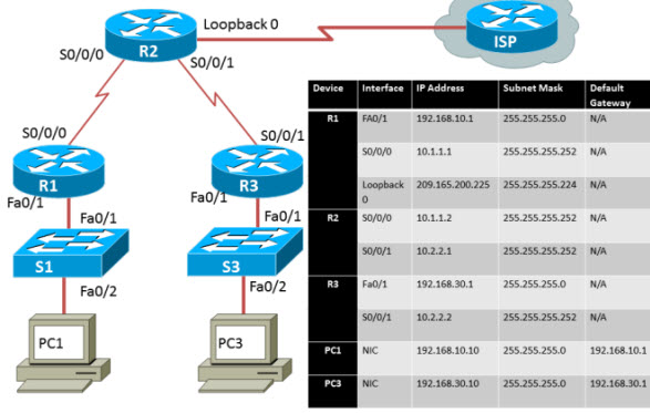
Look at the above diagram, we will be using three routers, a loop back connection, two switches (which we will leave them at their default configuration) and two PCs if you are using packet tracer or using real devices than cable the network. The next couple of steps are assuming you already know the material.
Next perform Basic Router Configurations (hostname, disable DNS lookup, EXEC password, message-of-the-day banner, and password for console and VTY connections, along with synchronous logging).
After that, configure the interfaces on R1, R2, and R3 (with the IP addresses from the addressing table (remember to include the clock rate on serial DCE interfaces).
Make sure that the IP addressing is correct and the interfaces are active by issuing the show ip interface brief command.
Test and configure ethernet interfaces on PC1 and PC3 (test by pinging the default gateway)
OK, now that all devices are connected we can start by configuring OSPF (so that each router knows about each other network). (On the R1 we are going to use the process ID of 1)
| 1 | R1(config)#router ospf 1 |
| 2 | R1(config-router)#network 192.168.10.0 0.0.0.255 area 0 |
| 3 | R1(config-router)#network 10.1.1.0 0.0.0.3 area 0 |
| 4 | *Aug 17 17:49:14.689: %OSPF-5-ADJCHG: Process 1, Nbr 209.165.200.225 on |
| 5 | Serial0/0/0 from LOADING to FULL, Loading Done |
| 6 | R1(config-router)# |
Next we will move to R2 and configure OSPF the output is:
| 01 | R2(config)#router ospf 1 |
| 02 | R2(config-router)#network 10.1.1.0 0.0.0.3 area 0 |
| 03 | *Aug 17 17:48:40.645: %OSPF-5-ADJCHG: Process 1, Nbr 192.168.10.1 on |
| 04 | Serial0/0/0 from LOADING to FULL, Loading Done |
| 05 | R2(config-router)#network 10.2.2.0 0.0.0.3 area 0 |
| 06 | R2(config-router)#network 209.165.200.224 0.0.0.31 area 0 |
| 07 | R2(config-router)# |
| 08 | *Aug 17 17:57:44.729: %OSPF-5-ADJCHG: Process 1, Nbr 192.168.30.1 on |
| 09 | Serial0/0/1 from LOADING to FULL, Loading Done |
| 10 | R2(config-router)# |
The last router (R3) is ready to be configured with OSPF (Again remember to use the process ID of 1)
| 1 | R3(config)#router ospf 1 |
| 2 | R3(config-router)#network 10.2.2.0 0.0.0.3 area |
| 3 | *Aug 17 17:58:02.017: %OSPF-5-ADJCHG: Process 1, Nbr 209.165.200.225 on |
| 4 | Serial0/0/1 from LOADING to FULL, Loading Done |
| 5 | R3(config-router)#network 192.168.30.0 0.0.0.255 area 0 |
| 6 | R3(config-router)# |
With OSPF setup you want to verify that you have full network connectivity (Every device should be able to ping each other) This is R1′s output of the command show ip route Also R1 was able to ping 192.168.30.1
| 01 | R1#show ip route |
| 02 | <output omitted> |
| 03 | O 192.168.30.0/24 [110/1563] via 10.1.1.2, 00:33:56, Serial0/0/0 |
| 04 | C 192.168.10.0/24 is directly connected, FastEthernet0/1 |
| 05 | 209.165.200.0/27 is subnetted, 1 subnets |
| 06 | O 209.165.200.225 [110/782] via 10.1.1.2, 00:33:56, Serial0/0/0 |
| 07 | 10.0.0.0/8 is variably subnetted, 3 subnets, 2 masks |
| 08 | O 10.2.2.0/30 [110/1562] via 10.1.1.2, 00:33:56, Serial0/0/0 |
| 09 | C 10.1.1.0/30 is directly connected, Serial0/0/0 |
| 10 | |
| 11 | R1#ping 192.168.30.1 |
| 12 | |
| 13 | Type escape sequence to abort. |
| 14 | Sending 5, 100-byte ICMP Echos to 192.168.30.1, timeout is 2 seconds: |
| 15 | !!!!! |
| 16 | Success rate is 100 percent (5/5), round-trip min/avg/max = 32/32/32 ms |
This output of R2 when issuing the command show ip route also R2 is able to ping 192.168.30.1 and 192.168.10.1
| 01 | R2#show ip route |
| 02 | <output omitted> |
| 03 | O 192.168.30.0/24 [110/782] via 10.2.2.2, 00:33:04, Serial0/0/1 |
| 04 | O 192.168.10.0/24 [110/782] via 10.1.1.1, 00:33:04, Serial0/0/0 |
| 05 | 209.165.200.0/27 is subnetted, 1 subnets |
| 06 | C 209.165.200.224 is directly connected, Loopback0 |
| 07 | 10.0.0.0/8 is variably subnetted, 4 subnets, 2 masks |
| 08 | C 10.2.2.0/30 is directly connected, Serial0/0/1 |
| 09 | C 10.1.1.0/30 is directly connected, Serial0/0/0 |
| 10 | |
| 11 | R2#ping 192.168.30.1 |
| 12 | |
| 13 | Type escape sequence to abort. |
| 14 | Sending 5, 100-byte ICMP Echos to 192.168.30.1, timeout is 2 seconds: |
| 15 | !!!!! |
| 16 | Success rate is 100 percent (5/5), round-trip min/avg/max = 16/16/16 ms |
| 17 | R2#ping 192.168.10.1 |
| 18 | |
| 19 | Type escape sequence to abort. |
| 20 | Sending 5, 100-byte ICMP Echos to 192.168.10.1, timeout is 2 seconds: |
| 21 | !!!!! |
| 22 | Success rate is 100 percent (5/5), round-trip min/avg/max = 16/16/16 ms |
This last output of R3 when using the command show ip route. R3 is able to ping 209.165.200.225 and 192.168.10.1
| 01 | R3#show ip route |
| 02 | <output omitted> |
| 03 | C 192.168.30.0/24 is directly connected, FastEthernet0/1 |
| 04 | O 192.168.10.0/24 [110/1563] via 10.2.2.1, 00:32:01, Serial0/0/1 |
| 05 | 209.165.200.0/27 is subnetted, 1 subnets |
| 06 | O 209.165.200.225 [110/782] via 10.2.2.1, 00:32:01, Serial0/0/1 |
| 07 | 10.0.0.0/8 is variably subnetted, 3 subnets, 2 masks |
| 08 | C 10.2.2.0/30 is directly connected, Serial0/0/1 |
| 09 | O 10.1.1.0/30 [110/1562] via 10.2.2.1, 00:32:01, Serial0/0/1 |
| 10 | |
| 11 | R3#ping 209.165.200.225 |
| 12 | |
| 13 | Type escape sequence to abort. |
| 14 | Sending 5, 100-byte ICMP Echos to 209.165.200.225, timeout is 2 seconds: |
| 15 | !!!!! |
| 16 | Success rate is 100 percent (5/5), round-trip min/avg/max = 16/16/16 ms |
| 17 | R3#ping 192.168.10.1 |
| 18 | |
| 19 | Type escape sequence to abort. |
| 20 | Sending 5, 100-byte ICMP Echos to 192.168.10.1, timeout is 2 seconds: |
| 21 | !!!!! |
| 22 | Success rate is 100 percent (5/5), round-trip min/avg/max = 32/32/32 ms |
Now that all devices can ping each other we can start configuring PPP encapsulation on the serial interfaces. Type the command show interface serial0/0/0 in R1 notice in the output the encapsulation type, which is HDLC. This is the default encapsulation on serial interfaces with Cisco Routers. (let’s change that to PPP)
| 1 | R1#show interface serial0/0/0 |
| 2 | Serial0/0/0 is up, line protocol is up |
| 3 | Hardware is GT96K Serial |
| 4 | Internet address is 10.1.1.1/30 |
| 5 | MTU 1500 bytes, BW 128 Kbit, DLY 20000 usec, |
| 6 | reliability 255/255, txload 1/255, rxload 1/255 |
| 7 | Encapsulation HDLC, loopback not set |
| 8 | |
R2′s output from the show interface serial0/0/0 and show interface serial0/0/1:
| 01 | R2#show interface serial0/0/0 |
| 02 | Serial0/0/0 is up, line protocol is up |
| 03 | Hardware is GT96K Serial |
| 04 | Internet address is 10.1.1.2/30 |
| 05 | MTU 1500 bytes, BW 128 Kbit, DLY 20000 usec, |
| 06 | reliability 255/255, txload 1/255, rxload 1/255 |
| 07 | Encapsulation HDLC, loopback not set |
| 08 | |
| 11 | R2#show interface serial0/0/1 |
| 12 | Serial0/0/1 is up, line protocol is up |
| 13 | Hardware is GT96K Serial |
| 14 | Internet address is 10.2.2.1/30 |
| 15 | MTU 1500 bytes, BW 128 Kbit, DLY 20000 usec, |
| 16 | reliability 255/255, txload 1/255, rxload 1/255 |
| 17 | Encapsulation HDLC, loopback not set |
| 18 | |
R3′s output from the show interface serial 0/0/1 command:
| 1 | R3#show interface serial0/0/1 |
| 2 | Serial0/0/1 is up, line protocol is up |
| 3 | Hardware is GT96K Serial |
| 4 | Internet address is 10.2.2.2/30 |
| 5 | MTU 1500 bytes, BW 128 Kbit, DLY 20000 usec, |
| 6 | reliability 255/255, txload 1/255, rxload 1/255 |
| 7 | Encapsulation HDLC, loopback not set |
| 8 | |
So you see that all routers have the encapsulation of HDLC, if we were to put PPP on one end of a serial interface say R2′s S0/0/0 interface and leave HDLC on the other end what would happen? If you guessed that the link would go down you are correct. But also OSPF would get rid of that route in the routing table. You have to be careful when configuring PPP especially on a production network. You run the risk of making you network inoperable if you are not careful setting the different encapsulations.
To change the encapsulation from HDLC to PPP on R1, R2, and R3. Go to the interface of the serial connection and type encapsulation ppp. (yes it is really that simple). This is the following output from R1 on interface s0/0/0 (notice that OSPF will go down if you don’t configure the other side of the serial interface in this case R2′s serial0/0/0)
| 1 | R1(config)#interface serial 0/0/0 |
| 2 | R1(config-if)#encapsulation ppp |
| 3 | R1(config-if)# |
| 4 | *Aug 16 18:15:53.412: %OSPF-5-ADJCHG: Process 1, Nbr 209.165.200.225 on |
| 5 | Serial0/0/0 from FULL to DOWN, Neighbor Down: Interface down or |
| 6 | detached |
This is R2′s output for the encapsulation change from HDLC to PPP, again notice how OSPF is going down because of the different encapsulation. R3 is still running HDLC therefore the link is down.
| 1 | R2(config)#interface serial0/0/1 |
| 2 | R2(config-if)#encapsulation ppp |
| 3 | R2(config-if)# |
| 4 | *Aug 17 20:02:08.080: %OSPF-5-ADJCHG: Process 1, Nbr 192.168.30.1 on |
| 5 | Serial0/0/1 from FULL to DOWN, Neighbor Down: Interface down or |
| 6 | detached |
Change R1 and R3 to the proper encapsulation type so communication between the routers are again connected and to get OSPF working again. (This example on R3 notice that once the encapsulation was changed to PPP the link went back up and OSPF found an adjacent neighbor.)
| 1 | R3(config)#interface serial 0/0/1 |
| 2 | R3(config-if)#encapsulation ppp |
| 3 | R3(config-if)# |
| 4 | *Aug 17 20:04:27.152: %LINEPROTO-5-UPDOWN: Line protocol on |
| 5 | Interface Serial0/0/1, changed state to up |
| 6 | *Aug 17 20:04:30.952: %OSPF-5-ADJCHG: Process 1, Nbr 209.165.200.225 on |
| 7 | Serial0/0/1 from LOADING to FULL, Loading Done |
Verify that all routers are now running PPP by typing the command show interface [interface ID] (This example shows that R1 is running PPP for the encapsulation)
| 01 | R1#show interface serial0/0/0 |
| 02 | Serial0/0/0 is up, line protocol is up |
| 03 | Hardware is GT96K Serial |
| 04 | Internet address is 10.1.1.1/30 |
| 05 | MTU 1500 bytes, BW 128 Kbit, DLY 20000 usec, |
| 06 | reliability 255/255, txload 1/255, rxload 1/255 |
| 07 | Encapsulation PPP, LCP Open |
| 08 | Open: CDPCP, IPCP, loopback not set |
This shows both of R2′s serial interfaces, when issuing the show interface serial0/0/0 and show interface serial0/0/1 commands:
| 01 | R2#show interface serial 0/0/0 |
| 02 | Serial0/0/0 is up, line protocol is up |
| 03 | Hardware is GT96K Serial |
| 04 | Internet address is 10.1.1.2/30 |
| 05 | MTU 1500 bytes, BW 128 Kbit, DLY 20000 usec, |
| 06 | reliability 255/255, txload 1/255, rxload 1/255 |
| 07 | Encapsulation PPP, LCP Open |
| 08 | Open: CDPCP, IPCP, loopback not set |
| 11 | |
| 12 | R2#show interface serial 0/0/1 |
| 13 | Serial0/0/1 is up, line protocol is up |
| 14 | Hardware is GT96K Serial |
| 15 | Internet address is 10.2.2.1/30 |
| 16 | MTU 1500 bytes, BW 128 Kbit, DLY 20000 usec, |
| 17 | reliability 255/255, txload 1/255, rxload 1/255 |
| 18 | Encapsulation PPP, LCP Open |
| 19 | Open: CDPCP, IPCP, loopback not set |
| 20 | |
R3′s output when issuing the show interface serial0/0/1 command:
| 01 | R3#show interface serial 0/0/1 |
| 02 | Serial0/0/1 is up, line protocol is up |
| 03 | Hardware is GT96K Serial |
| 04 | Internet address is 10.2.2.2/30 |
| 05 | MTU 1500 bytes, BW 128 Kbit, DLY 20000 usec, |
| 06 | reliability 255/255, txload 1/255, rxload 1/255 |
| 07 | Encapsulation PPP, LCP Open |
| 08 | Open: CDPCP, IPCP, loopback not set |
Now that all routers are using a different encapsulation protocol (PPP) we can also give the protocol some authentication. The first one we will use is (PAP) password authentication protocol. PAP is not a secure authentication protocol. Passwords are sent using plain text and only authenticates once.
To set up PAP the username and password must match the other router.
So for this example R1′s username is R1 and the password is knowing.
| 1 | R1(config)#username R1 password knowing |
Keep in mind that this information needs to be typed on R2 for PAP to work.
The example from R2′s username is R2 and the password is knowing.
| 1 | R2(config)#username R2 password knowing |
Again this information needs to be typed on R1 for PAP to work.
Back to R1 we want to go to the interface that R2 is connected to(interface s0/0/0) then we would type ppp authentication pap hit enter (notice the link went down between R1 and R2). Typeppp pap sent-username R2 password knowing This will send the username of R2 and the password of “knowing” to R2. R2 will check the username and password and because they match R2′s username and password PPP will be authenticated.
| 1 | R1(config)#int s0/0/0 |
| 2 | R1(config-if)#ppp authentication pap |
| 3 | R1(config-if)# |
| 4 | *Aug 22 18:58:57.367: %LINEPROTO-5-UPDOWN: Line protocol on |
| 5 | Interface Serial0/0/0, changed state to down |
| 6 | R1(config-if)# |
| 7 | *Aug 22 18:58:58.423: %OSPF-5-ADJCHG: Process 1, Nbr 209.165.200.225 on |
| 8 | Serial0/0/0 from FULL to DOWN, Neighbor Down: Interface down or detached |
| 9 | R1(config-if)#ppp pap sent-username R2 password knowing |
Let’s do the same thing with R2 as we did with R1 but remember to type R1′s username (R1) and password (knowing) on R2′s interface that connects to R1 (serial0/0/0) Also notice that the link between R1 and R2 went back up.
| 1 | R2(config)#interface Serial0/0/0 |
| 2 | R2(config-if)#ppp authentication pap |
| 3 | R2(config-if)#ppp pap sent-username R1 password knowing |
| 4 | R2(config-if)# |
| 5 | *Aug 23 16:30:33.771: %LINEPROTO-5-UPDOWN: Line protocol on |
| 6 | Interface Serial0/0/0, changed state to up |
The way to set up CHAP is fundamentally the same. Looking at R2 we are still going to be using the username and password. However in this case the username will be R3 instead of R2 because of the three-way handshake CHAP uses. The password will be “knowing”. We than go into the serial interface that R3 is connected to (s0/0/1) and type ppp authentication chap(Notice how the link went down) Now that R1 and R2 are working with PAP with PPP we can put CHAP between R2 and R3. CHAP stands for (Challenge Handshake Authentication Protocol) because of the challenge CHAP is a stronger authentication than PAP. CHAP also encrypts the password so it is not sent in plain text.
| 01 | R2(config)#username R3 password knowing |
| 02 | R2(config)#int s0/0/1 |
| 03 | R2(config-if)#ppp authentication chap |
| 04 | R2(config-if)# |
| 05 | *Aug 23 18:06:00.935: %LINEPROTO-5-UPDOWN: Line protocol on |
| 06 | Interface Serial0/0/1, changed state to down |
| 07 | R2(config-if)# |
| 08 | *Aug 23 18:06:01.947: %OSPF-5-ADJCHG: Process 1, Nbr 192.168.30.1 on |
| 09 | Serial0/0/1 from FULL to DOWN, Neighbor Down: Interface down or detached |
| 10 | R2(config-if)# |
Let’s do the same thing for R3 as we did for R2′s serial interface link (0/0/1) The username will be R2 and the password will be “knowing”. (because of the three-way handshake CHAP uses) Also notice the link between R3 and R2 it went back up and OSPF is working again.
| 1 | R3(config)#username R2 password knowing |
| 2 | *Aug 23 18:07:13.074: %LINEPROTO-5-UPDOWN: Line protocol on |
| 3 | Interface Serial0/0/1, changed state to up |
| 4 | R3(config)#int s0/0/1 |
| 5 | R3(config-if)# |
| 6 | *Aug 23 18:07:22.174: %OSPF-5-ADJCHG: Process 1, Nbr 209.165.200.225 on |
| 7 | Serial0/0/1 from LOADING to FULL, Loading Done |
| 8 | R3(config-if)#ppp authentication chap |
More Related Topics:
That’s that! You know have PPP setup and some authentication. Between R1 and R2 the authentication is PAP and between R2 and R3 the authentication is CHAP. You should be able to ping all the devices within the topology diagram.
Article from https://ciscoskills.net/2011/01/18/basic-ppp-configuration/
More Related Topics:
How to Configure PPP on Cisco Router?

Expertise Builds Trust
20+ Years • 200+ Countries • 21500+ Customers/Projects
CCIE · JNCIE · NSE7 · ACDX · HPE Master ASE · Dell Server/AI Expert