
In this article we will describe the recommended cabling configurations for a StackPower stack. There are two types of StackPower cables. The cable in Figure 1 connects a Catalyst 3750-X switch to another 3750-X switch in a power stack. The cable in Figure 2 is used between a Catalyst 3750-X or 3560-X switch and the XPS-2200.
Note: The XPS 2200 eXtended Power Supply for the Cisco Catalyst 3750-X will not be available until December 2010. Until that time, Power Stacking can be done with Ring Topology and a maximum of four Catalyst 3750-X switches.
Note: StackPower and XPS cables are keyed and have colored bands on the ends to help you understand what cable plugs into what switch or XPS. StackPower cable has colors bands on the cable ends, green on one end and yellow on the other end (Figure1). This cable can be used between Catalyst 3750-X switches or to an XPS-2200. Review the colors on the 3750-X chassis in Figure 10.
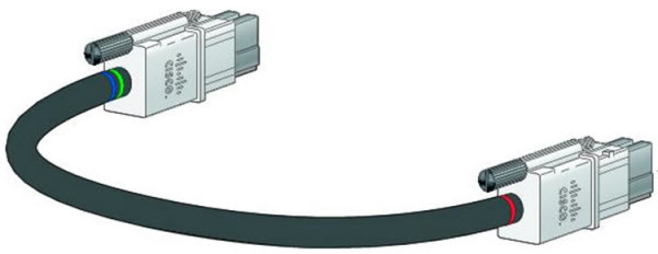
Note that the connector with the blue band can only connect into a Catalyst 3750-X switch while the connector with the yellow band (Figure2) can connect to a Catalyst 3750-X or an XPS. An XPS cable has a color band on the cable ends as well, red on one end and yellow on the other end. This cable can only be used to connect Catalyst 3750-X or 3560-X switch to an XPS. Note that the connector with the red band can only connect to an XPS while the connector with the green and blue band can connect to Catalyst 3750-X or 3560-X switch. Review the colors on the XPS-2200 chassis Figure11.
Both cable types are available in two lengths.
Table1: StackPower Cables
| Part Number | Cable Type | Length |
| CAB-SPWR-30CM | Catalyst 3750-X power stack cable | 0.3 meter |
| CAB-SPWR-150CM | Catalyst 3750-X power stack cable | 1.5 meter |
Figure1: StackPower Cable for Use between Cisco Catalyst 3750-X Switches or 3750-X (Green) and XPS-2200 (Yellow)
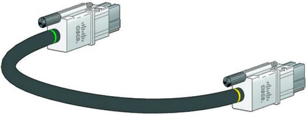
Table1: XPS-2200 Cables
| Part Number | Cable Type | Length |
| CAB-XPS-58CM | XPS-2200 connector cable | 0.58 meter |
| CAB-XPS-150CM | XPS-2200 connector cable | 1.5 meter |
Figure2: Use between a Cisco Catalyst 3750-X (Blue/Green) and a XPS-2200 (Red)
You can configure a ring topology power stack with up to four switches (Figure3) or use the XPS-2200 to configure a star topology with up to 9 switches (Figure4). The configuration in Figure 4 uses both of the supplied 0.3-meter StackPower cables and one 1.5-meter cable. In these examples, the switches are stacked in a vertical rack or on a table. The red band connects only to an XPS while the Green or Green/Blue connector connects to Catalyst 3750-X or 3560-X switch.
Figure3: StackPower Ring Topology
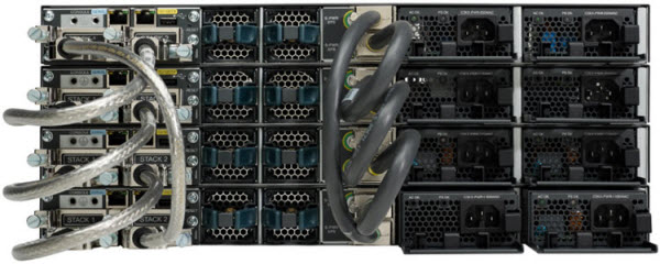
Figure4 shows nine switches connected to an XPS-2200 expandable power supply in a star topology.
Figure4: StackPower Star Topology
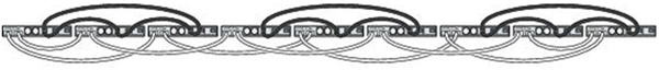
Because a power stack can include a maximum of four switches in a Ring topology, Figure5 shows shows a nine-switch data stack configured with three power stacks. You can configure multiple power stacks within a data stack, but a power stack that spans multiple data stacks is not supported.
Figure5: Power Stacking Catalyst 3750-X Switches within a Switch Data Stack
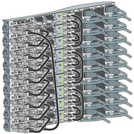
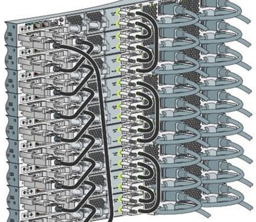
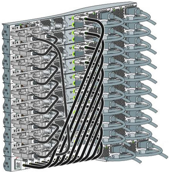
Figure6 and Figure7 are examples of recommended configurations when the switches are mounted side-by-side. Use the 1.5-meter StackPower cables to connect the switches. These configurations provide redundant connections.
Figure6: PowerStack: Four Switches in a Side-by-Side Mounting Configuration
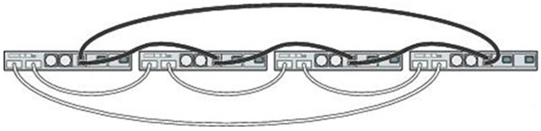
Figure7: Power Stacking within a Nine-Switch Data Stack in a Side-by-Side Mounting Configuration
StackPower Partitioning Examples
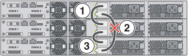
Figure8 and Figure9 show StackPower stacks of Catalyst 3750-X switches with failover conditions. In Figure8, the StackPower cable 2 is faulty. Therefore, this stack does not provide redundancy.
Figure8: Example of a StackPower Stack with a Failover Condition

In Figure9, StackPower port B on the center switch has failed and this stack partitions into two stacks. The top two switches share power, and the bottom switch is now a separate stack.
Figure9: Example of a Partitioned StackPower Stack with a Failover Condition
StackPower connections
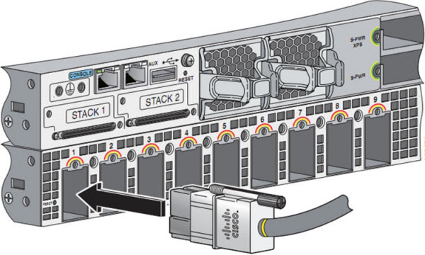
Figure10 shows the StackPower connections to the StackPower ports on the Cisco Catalyst 3750-X. Note the markings on the chassis indicate the color on the cable that can be connected.
Figure10: StackPower connections
The following are steps for making Shared Power or XPS-2200 Power connections.
Step1. Remove the dust covers from the StackPower cable connectors.
Step2. Connect the cable with a green or Green/Blue stripe to either XPS connector on the 3750-X.
Step3. Connect theother end of the cable with the yellow to a S-PWR port on another Catalyst 3750-X switch if using StackPower power sharing, or to an XPS-2200 power supply to configure redundancy. The cable end with the Red band is can only be connected to the XPS-2200.
Step1. Hand-tighten the captive screws to secure the StackPower connectors in place
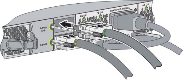
Figure11 shows the StackPower cables conenctions to the XPS-2200.
Figure11: XPS-2200 Cable Connections
Guide resource from https://www-tss.cisco.com
More Related Cisco 3750 Tutorials:
Cisco 3750 Stacking Configuration
Cisco 3750-X Series Switches-Cisco StackPower Efficient Use of Power

Expertise Builds Trust
20+ Years • 200+ Countries • 21500+ Customers/Projects
CCIE · JNCIE · NSE7 · ACDX · HPE Master ASE · Dell Server/AI Expert
