
We once compared the main Cisco ASA 5585-X models, Cisco ASA 5585-X with SSP-10, ASA 5585-X SSP-20, ASA 5585-X SSP-40 and ASA 5585-X SSP-60. With two 8-port 10 Gigabit Ethernet modules and one Security Services Processor (SSP)-40 or SSP-60 module, Cisco ASA 5585-X can support up to 20 10 Gigabit Ethernet ports in 2 rack unit (2RU) chassis. With two 20-port 1 Gigabit Ethernet modules and one SSP module, Cisco ASA 5585-X can support up to 50 1 Gigabit Ethernet ports in 2RU chassis.
We also read the main features of ASA 5585-X series. How to start a Cisco asa 5585-X? You can read the quick guide to start a Cisco ASA 5585-x series.
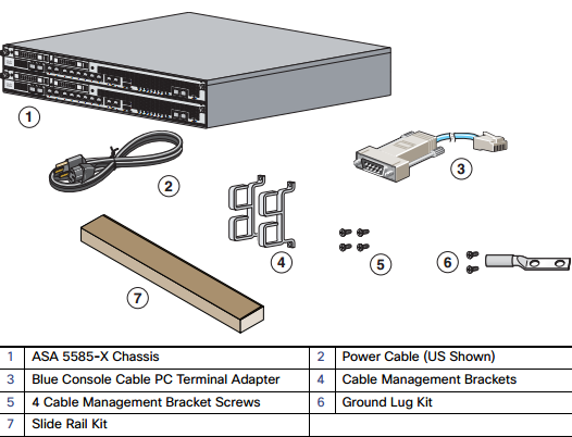
First of all, let’s check the main package contents of Cisco ASA 5585-X.
Note: The ASA 5585-X with SSP-10, SSP-20, or SSP-40 ships with one power supply module installed and one power cable. The ASA 5585-X with SSP-60, ships with two power supply modules installed and two power cables.
Power on the ASA
1. Attach the power cable to the back of the ASA. If you have redundant power supplies, you must connect both power cables to the back of the chassis.
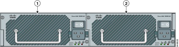
| 1 | Power Supply Module (PS0) | 2 | Power Supply Module (PS1) |
2. Connect the power cables to the electrical outlets.
3. Power on the ASA. If you have redundant power supplies, you must power on both modules.
4. Check the Power LED on the front of the ASA; the AC ON indicator should be green, the FAN ON indicator should be green and the OUT OK indicator should be off.
Network Considerations for Multiple SSPs
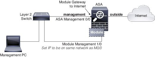
The ASA SSP resides in slot 0 (bottom). A second SSP (or network module) can be installed in slot 1 (top). When you install a non-ASA SSP in slot 1, all non-management interfaces belong to the ASA in slot 0, while the management interfaces belong to the module. If you install dual ASA SSPs, then they are completely independent systems.
Default Configuration for Management
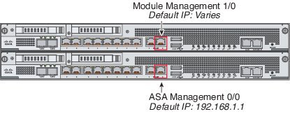
See the following table for default configurations for the Management interfaces depending on which module is installed in slot 1.
Note that the left-hand Management interface (when facing the back of the chassis) is not configured by default.
All management traffic to and from the non-ASA SSP must enter and exit the Management 1/0 or 1/1 interface. Because this interface is not an ASA data interface, traffic cannot pass through the ASA over the backplane; you need to physically cable the management interface to an ASA interface. Non-ASA SSPs typically need Internet access for updates. See the following typical cabling setup to allow SSP access to the Internet through the ASA management interface. Other options are possible, depending on how you want to connect your network; for example, you can make the Management 1/0 interface outside facing; or you can route between it and a different ASA interface if you have an inside router; and so on.
Connect Interface Cables and Verify Connectivity
1. Cable the management and data interfaces. See Network Considerations for Multiple SSPs for a sample cabling scenario.
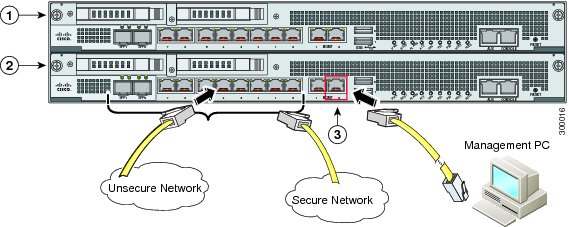
| 1 | (Optional) Slot 1 module, multiple types available. | 2 | Slot 0 ASA SSP |
| 3 | ASA SSP Management 0/0 interface (RJ-45) |
2. If you do not use the Management 0/0 for ASA management, you need to configure a data interface for management. Do one of the following, then recable the computer so it is on the new management network:
- –Connect to the console port to configure a data interface for management with CLI. See the Getting Started chapter in the general operations configuration guide for detailed steps.
- –Temporarily connect to Management 0/0, launch ASDM (see Launch ASDM), and configure a data interface for management.
3. If you are using the fiber interfaces, you need an SFP+ module for 10-Gigabit Ethernet (a license may be required) or an SFP module for Gigabit Ethernet. (SFP or SFP+ modules are not included.)
The interfaces available depend on your model.
4. Check the LINK/ACT indicators to verify interface connectivity.
5. For software module configuration, see the ASA FirePOWER quick start guide, ASA CX quick start guide, or IPS quick start guide on Cisco.com.
Launch ASDM
Using ASDM, you can use wizards to configure basic and advanced features. ASDM is a graphical user interface that allows you to manage the ASA using a web browser. See the ASDM release notes on Cisco.com for the requirements to run ASDM.
How to Launch ASDM?
1. On the computer connected to the ASA Management 0/0 interface, launch a web browser.
2. In the Address field, enter the following URL: https://192.168.1.1/admin. The Cisco ASDM web page appears.
3. Click one of the available options: Install ASDM Launcher, Run ASDM, or Run Startup Wizard.
4. Follow the onscreen instructions to launch ASDM according to the option you chose. The Cisco ASDM-IDM Launcher appears.
5. Leave the username and password fields empty, and click OK. The main ASDM window appears.
…
Run ASDM Wizards and Advanced Configuration
ASDM includes many wizards to configure your security policy. See the Wizards menu for all available wizards, including the Startup Wizard for initial deployment. To continue configuring your ASA, see the documents available for your software version at https://www.cisco.com/c/en/us/td/docs/security/asa/roadmap/asaroadmap.html
Any more about Cisco ASA 5500-X series? You can read the related article of Cisco ASA 5585-X Comparison
More Related
NGFW-Cisco ASA with FirePOWER Services

Expertise Builds Trust
20+ Years • 200+ Countries • 21500+ Customers/Projects
CCIE · JNCIE · NSE7 · ACDX · HPE Master ASE · Dell Server/AI Expert
