
We sometimes need to connect two switches or make them not access with each other. How to?
In this post, let’s discuss.
- How can the network interoperate?
In general, how can two computers communicate with each other? How can them not visit each other?
The easiest way is to use the network segment to solve, let’s take an example.
(1) Two computers cannot access each other
Assumption:
PC1 IP address: 192.168.1.1/24
PC2 IP address: 192.168.2.1/24
To test the connectivity between PC1 and PC2: The easiest way is to use PC1 to PingPC2 and check the Ping results.
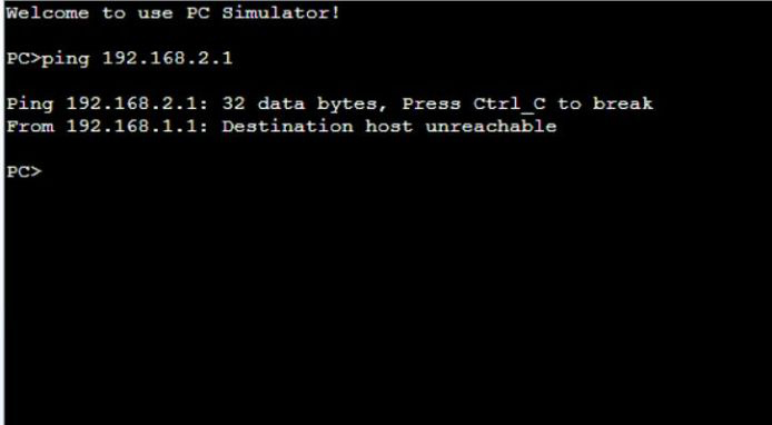
Obviously, the ping fails. The IPs of PC1 and PC2 are in different network segments, so they cannot be pinged.
So what kind of situation can ping through?
(2) How to intercommunicate
Assumption:
PC1 IP address: 192.168.1.1/24
PC2 IP address: 192.168.1.2/24
PC3 IP address: 192.168.1.3/24
If they are all in the same network segment, test whether pc1 can communicate with pc2 and pc3, just use pc1 to ping pc2 and pc3.
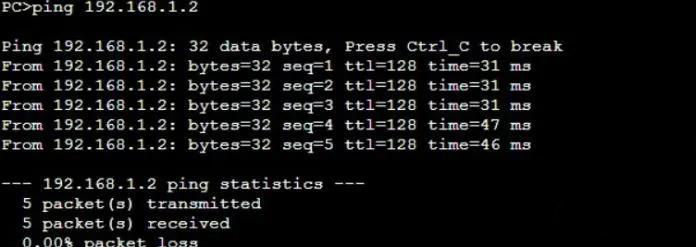
pc1 to ping pc2
[PC>ping 192.168.1.2
Ping 192.168.1.2: 32 data bytes, Press Ctrl_C to break
From 192.168.1.2: bytes=32 seq=1 ttl=128 time=32 ms
From 192.168.1.2: bytes=32 seq=2 ttl=128 time=31 ms]
pc1to ping pc3
[PC>ping 192.168.1.3
Ping 192.168.1.3: 32 data bytes, Press Ctrl_C to break
From 192.168.1.3: bytes=32 seq=1 ttl=128 time=31 ms
From 192.168.1.3: bytes=32 seq=2 ttl=128 time=31 ms]
Obviously, both can be pinged, because PC1-PC3 are in the same network segment and use the same gateway.
So the question is, how to make the IP of the same network segment not communicate with each other? How to make the IP of different network segments communicate with each other? Here we need to introduce VLAN.
- Divide VLANs to achieve mutual access and blockade of the network
Above we have demonstrated the simplest interoperability and interoperability of the network. Without other settings, the IP addresses of the same network segment can communicate, but the IP addresses of different network segments cannot communicate. In the actual project, it is not so simple. Let’s look at how to realize the intercommunication and blocking between different VLANs and different network segments.
Assumption:
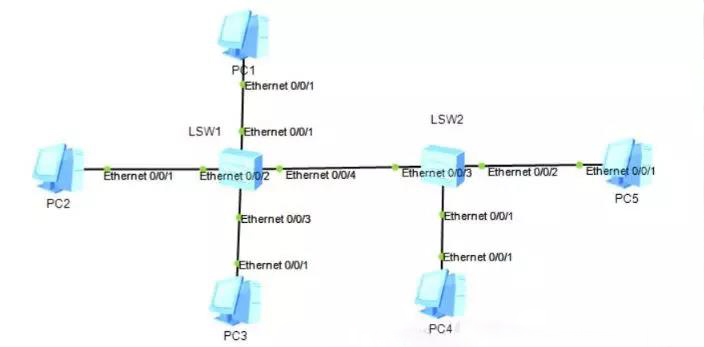
PC1 IP address: 192.168.1.1/24, connected to LSW1 switch, port Ethernet 0/0/1
PC2 IP address: 192.168.1.2/24, connected to LSW1 switch, port Ethernet 0/0/2
PC3 IP address: 192.168.1.3/24, connect to LSW1 switch, port Ethernet 0/0/3
PC4 IP address: 192.168.1.4/24, connected to LSW2 switch, port Ethernet 0/0/1
Now, let PC1 and PC2 communicate with each other, PC1 and PC3 cannot communicate with each other, and PC1 and PC4 cannot communicate with each other. How to configure the switch? (Today we will take Huawei switches as an example).
Switch Setting:
(1) Set LSW1 Switch
<Huawei>system-view: Enter system view
[Huawei]sysname sw1: Name the switch
[sw1]vlan 10: Create VLAN10
[sw1-vlan10]vlan 20: Create VLAN20
[sw1-vlan20]display vlan: Display VLAN information
[sw1-vlan20]quit : Return to the previous view
[sw1]interface Ethernet 0/0/1: Enter the Ethernet interface 0/0/1
[sw1-Ethernet0/0/1]port link-type access: Configure the interface type as Access
[sw1-Ethernet0/0/1]port default vlan 10: Assign interface to VLAN10
[sw1-Ethernet0/0/1]quit: Return to the previous view
[sw1]interface Ethernet 0/0/2: Enter Ethernet interface 0/0/2
[sw1-Ethernet0/0/2]port link-type access: Configure the interface type as Access
[sw1-Ethernet0/0/2]port default vlan 10: Assign interface to VLAN10
[sw1-Ethernet0/0/2]quit: Return to the previous view
[sw1]interface Ethernet 0/0/3: Enter Ethernet interface 0/0/3
[sw1-Ethernet0/0/3]port link-type access: Configure the interface type as Access
[sw1-Ethernet0/0/3]port default vlan 20: Assign interface to VLAN20
[sw1-Ethernet0/0/3]display vlan: Display VLAN information
Summary: In LSW1, pc1 and pc2 are allocated to vlan10, and pc3 is allocated to vlan20.
(2) Set LSW2 Switch
The commands are similar to the above, so I won’t comment one by one.
<Huawei>system-view
[Huawei]sysname sw2
[sw2]vlan 10: Create VLANs in batches
[sw2]display vlan
[sw2]interface Ethernet 0/0/1: Enter the Ethernet interface 0/0/1 of pc4
[sw2-Ethernet0/0/1]port link-type access: Configure the interface type as Access
[sw2-Ethernet0/0/1]port default vlan 10: Assign interface to VLAN10
[sw2-Ethernet0/0/2]display vlan
In LSW2, pc4 is mainly divided into vlan10
(3) Verify VLAN
a.Test the connectivity of PC1 and PC2.
Because they are in the same VLAN and in the same network segment, PC1 and PC2 can ping through.
b. Test the connectivity of PC1 and PC3
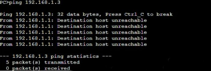
Although the IP addresses of PC1 and PC3 are in the same network segment, PC1 and PC3 are not in the same VLAN, so PC1 and PC3 cannot be pinged (PC1 belongs to vlan10, PC3 belongs to vlan20).
c.Test the connectivity of PC1 and PC4

Obviously, PC1 and PC4 cannot be pinged. Why is this?
Although PC1 and PC4 are in the same VLAN and also in the same network segment, the Lsw1 and Lsw2 switches are not configured with trunk ports, and the access ports are not tagged with the trunk port, so the ping fails!
So the question is, how can pc1 and pc4 communicate with each other?
- How to make the switches communicate with each other
As we mentioned above, pc1 belongs to the LSW1 switch and PC2 belongs to the SLW2 switch. Although PC1 and PC4 are divided into the same VLAN and the IP address is in the same network segment, they still cannot communicate with each other, mainly because the trunk interface is not configured. Let’s configure it.
(1) Set LSW1Switch
[sw1]interface Ethernet 0/0/4: Enter the interface 0/0/4 connecting switch 1 and switch 2
[sw1-Ethernet0/0/4]port link-type trunk: Configure the interface type as trunk
[sw1-Ethernet0/0/4]port trunk allow-pass vlan 10 20: VLAN10 and vlan20 allowed through the trunk port.
(2) Set LSW2 Switch
[sw2]interface Ethernet 0/0/3: Enter the interface 0/0/3 connecting switch 1 and switch 2
[sw2-Ethernet0/0/3]port link-type trunk: Configure the interface type as trunk
[sw2-Ethernet0/0/3]port trunk allow-pass vlan 10 20: VLAN10 and vlan20 allowed through the trunk port.
(3) Verify trunk interface configuration:
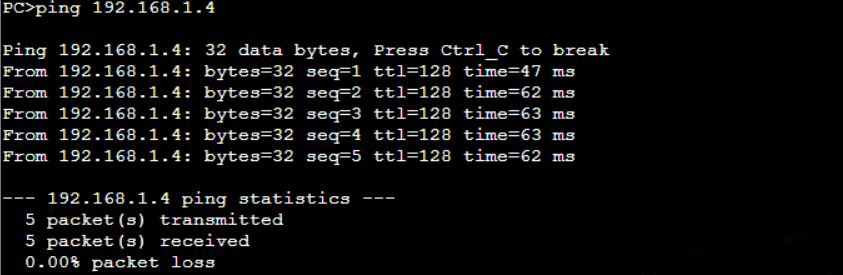
PC1 and PC4 can ping, because the trunk interface is set between the switches, so that different VLANs can pass through other switches!
Finally, let’s summarize:
- Under what circumstances will we divide VLANs?
Only when the network is logically isolated will VLAN be divided! In different VLANs, even in the same network segment, it cannot be pinged successfully.
- Under what circumstances will we configure the trunk interface?
To connect the switch to the switch, you need to set up a trunk interface.
If you have different opinions, please leave your comment.
Related Topics:
Buyer Guide: How to Select Access Layer Switches for Enterprise?
Huawei Switches Vs. Juniper Switches
Cisco Switches vs. Dell Switches

Expertise Builds Trust
20+ Years • 200+ Countries • 21500+ Customers/Projects
CCIE · JNCIE · NSE7 · ACDX · HPE Master ASE · Dell Server/AI Expert
