
We talked about the new Cisco ASA 5506-X a lot before. And users like to discuss about this replacement of the old ASA 5505 series. No matter what’s your experience with the ASA 5506-X, it’s popular now. In this article we will mainly share more info and start guide of the ASA 5506W-X.
The Cisco ASA 5506W-X, and also the ASA 5506-X and 5506H-X are part of the ASA 5500-X of next-generation mid-range ASAs and are built on the same security platform as the rest of the ASA family.
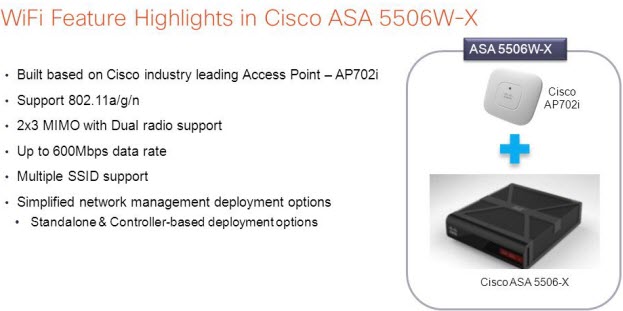
The ASA 5506W-X includes a Cisco Aironet 702i wireless access point integrated into the ASA. The access point connects to the ASA internally over the GigabitEthernet 1/9 interface. All wifi clients belong to the GigabitEthernet 1/9 network. The ASA security policy determines how the wifi network can access any networks on other interfaces. The access point does not contain any external interfaces or switch ports.
The access point includes an autonomous Cisco IOS image, which enables individual device management. You can install the lightweight image if you want to add the ASA 5506W-X to a Cisco Unified Wireless Network and use a wireless LAN controller.
This ASA is a smaller form-factor chassis, intended primarily for desktop or wall-mounting, although one or two can be mounted in a single rack shelf.
The ASA has a standard 1 RU chassis.
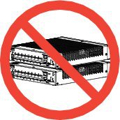
Caution Here: Do not stack the ASA chassis on top of another ASA chassis. If you stack the units, they will overheat, which causes the units to power cycle.
ASA 5506W-X Wireless Features
The ASA 5506W-X supports two high-performing spatial stream rates over a deployable distance with high reliability when serving clients.
The ASA 5506W-X contains two simultaneous dual-band radios (2.4-GHz and 5-GHz 802.11n MIMO radios) in a controller-based mode or autonomous mode. It has integrated internal antennas that support full inter-operability with leading 802.11n clients. The radio hardware supports Unified, FlexConnect, and Monitor-mode.
The ASA 5506W-X has the following processor features:
- 128 MB NAND flash size
- 1 MB NOR flash size
- 128 MB DDR2 memory bus, x32
The 2.4 GHz and 5 GHz 802.11n radios have the following features:
- 802.11n standard compliant
- A-MPDU TX
- HT Duplicate Mode
- 2TX x 2RX
- 2-spatial streams, 300 Mbps PHY rate
- Maximal ratio combining (MRC)
- Cyclic Shift Diversity (CSD)
- MCS0-MCS15; Short or Long Guard Intervals
- DFS for UNII-2 and UNII-2 Extended channels, including 0.5us radar pulse detection
The ASA 5506W-X is configured with four single-band, inverted-F antennas (two 2.4-GHz and two 5-GHz), which are evenly spaced inside the top of the chassis. Peak gains are approximately 3 dBi in the 2.4-GHz band and 5 dBi in the 5-GHz band.
By the Way, ASA 5506H-X Features: The ASA 5506H-X is a hardened version of the 5506-X with a ruggedized chassis, power supply, SSD, and four ports instead of eight. It is ruggedized because it supports a much wider industrial operational temperature range (-20C to 60C), meets the harsh EMI and environmental criteria for the IEC1613 and IEC 61850-3 power substation standards, and meets IEC60529 IP40 for ingress protection.
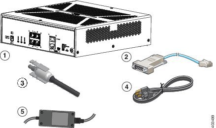
Package Contents of the ASA 5506W-X & ASA 5506-X
The following figure shows the package contents for the ASA 5506-X and ASA 5506W-X.
Note: The contents are subject to change and your exact contents might contain additional or fewer items.
ASA 5506W-X and 5506-X Package Contents
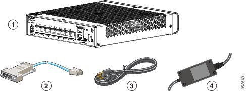
| 1 | Chassis | 2 | Blue Console Cable PC Terminal Adapter |
| 3 | Power cord | 4 | Brick power supply |
The figure2 shows the package contents for the ASA 5506H-X.
Figure2. ASA 5506H-X Package Contents
| 1 | Chassis | 2 | Blue Console Cable PC Terminal Adapter |
| 3 | Power cord retention lock | 4 | Power cord |
| 5 | Power supply |
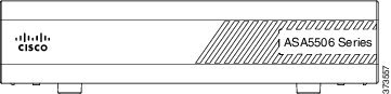
Front Panel
The following figure shows the front panel of the ASA 5506-X. The ASA 5506W-X has an identical front panel.
Note that there are no connectors or LEDs on the front panel.
Rear Panel
The following figure shows the rear panel of the ASA 5506-X.
The 5506W-X has an identical rear panel.
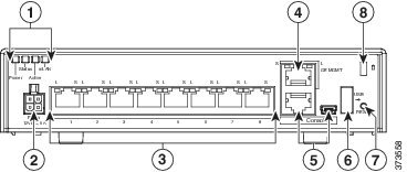
| 1 | Status LEDs | The locations and meanings of the status LEDs are described in Status Lights. | ||||
| 2 | Power cord socket | The chassis power-supply socket. See Power Supply for more information about the chassis power supply.
| ||||
| 3 | Network data ports | Eight Gigabit Ethernet RJ-45 (8P8C) network I/O interfaces. The ports are numbered (from left to right) 1, 2, 3, 4, 5, 6, 7, 8. Each port includes a pair of LEDs, one each for connection status and link status. The ports are named and numbered Gigabit Ethernet 1/1 through Gigabit Ethernet 1/8. See Network Ports for additional information. | ||||
| 4 | Management port | A Gigabit Ethernet interface restricted to network management access only. Connect with an RJ-45 cable. | ||||
| 5 | Console ports | Two serial ports, a mini USB Type B, and a standard RJ-45 (8P8C), are provided for management access via an external system. See Console Ports for additional information. | ||||
| 6 | USB port | A standard USB Type A port is provided that allows the attachment of an external device, such as mass storage. See Internal and External Flash Storage for additional information. | ||||
| 7 | Reset button | A small recessed button that if pressed for longer than three seconds resets the ASA to its default “as-shipped” state following the next reboot. Configuration variables are reset to factory default. However, the flash is not erased and no files are removed.
| ||||
| 8 | Lock slot | The slot accepts a standard Kensington T-bar locking mechanism for securing the ASA. |
The following figure shows the rear panel of the 5506H-X.
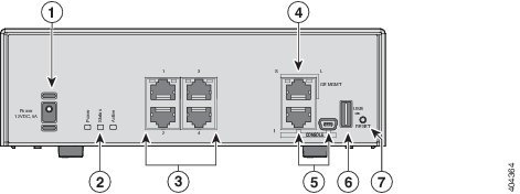
| 1 | Power cord socket. | The chassis power-supply socket. See Power Supply for more information about the chassis power supply.
| ||
| 2 | Status LEDs | The locations and meanings of the status LEDs are described in Status Lights. | ||
| 3 | Network data ports | Four Gigabit Ethernet RJ-45 (8P8C) network I/O interfaces. The ports are numbered (from top to bottom) 1, 2, 3, 4,. Each port includes a pair of LEDs, one each for connection status and link status. The ports are named and numbered Gigabit Ethernet 1/1 through Gigabit Ethernet 1/4. See Network Ports for additional information. | ||
| 4 | Management port | A Gigabit Ethernet interface restricted to network management access only. Connect with an RJ-45 cable. | ||
| 5 | Console ports | Two serial ports, a standard RJ-45 (8P8C), and a mini USB Type B, are provided for management access via an external system. See Console Ports for additional information. | ||
| 6 | USB port | A standard USB Type A port is provided that allows the attachment of an external device, such as mass storage. See Internal and External Flash Storage for additional information. | ||
| 7 | Reset button | A small recessed button that if pressed for longer than three seconds resets the ASA to its default “as-shipped” state following the next reboot. Configuration variables are reset to factory default. However, the flash is not erased and no files are removed.
|
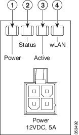
Status Lights
Facing the rear of the ASA 5506-X and ASA 5506W-X chassis, the status lights are located on the top left edge (facing the front of the chassis, they are in the back right corner of the top). The following figure shows the lights on the top left edge.
Facing the rear of the ASA 5506H-X the status lights, are located on the bottom left of the chassis. The network port lights are at the top sides of each network port. See Rear Panel for more information.
| LED | Description | |
| 1 | Power | Power supply status:
See Power Supply for additional power information specific to your specific ASA. |
| 2 | Status | System operating status:
|
| 3 | Active | Status of the failover pair:
|
| 4 | wLAN |
Not in use on the ASA 5506-X or the ASA 5506-H. Association status of the wireless connection on the ASA 5506W-X:
|
| Network port status | On the rear panel of the ASA 5506-X and ASA 5506W-X, a pair of LEDs (link status and connection status) for each of the eight Gigabit Ethernet network ports, and the Gigabit Ethernet management port. On the rear panel of the ASA 5506H-X, a pair of LEDs (link status and connection status) for each of the four Gigabit Ethernet network ports, and the Gigabit Ethernet Management port. Link status (L):
Connection-speed status (S):
|
Network Ports
There are eight 10/100/1000 baseT Ethernet network ports on the ASA 5506-X and ASA 5506W-X. Each RJ-45 (8P8C) copper port supports auto MDI/X as well as auto-negotiation for interface speed, duplex, and other negotiated parameters, and are MDI/MDIX compliant.
In addition, the ASA 5506W-X has a Gigabit Ethernet 1/9 port that is internal and connects to the WLAN module.
The ASA 5506H-X has four 10/100/1000 baseT Ethernet network ports. Each RJ-45 (8P8C) copper port supports auto MDI/X as well as auto-negotiation for interface speed, duplex, and other negotiated parameters, and are MDI/MDIX compliant.
Port Numbering of the ASA 5506W-X and ASA 5506-X
Looking at the rear of the ASA 5506-X and ASA 5506W-X, where the ports are located, port 1 is on the left, and port 8 is on the right, next to the console and management ports. Each port is accompanied by a pair of LEDs, one each for link status (L) and connection status (S). The ports are named and numbered Gigabit Ethernet 1/1 through Gigabit Ethernet 1/8. The ports are named and numbered Gigabit Ethernet 1/1 through Gigabit Ethernet 1/4.
The four ports on the ASA 5506H-X are numbered differently. Looking at the rear of the ASA 5506H-X where the ports are located, ports 1 and 3 are at the top from left to right. Ports 2 and 4 are on the bottom from left to right. The ports are between the Status LEDs and the console and management ports. The ports are named and numbered Gigabit Ethernet 1/1 through Gigabit Ethernet 1/4.
Console Ports of the ASA 5506W-X
The ASA has two external console ports, a standard RJ-45 port and a Mini USB Type B serial port. Only one console port can be active at a time. When a cable is plugged into the USB console port, the RJ-45 port becomes inactive. Conversely, when the USB cable is removed from the USB port, the RJ-45 port becomes active. The console ports do not have any hardware flow control. You can use the command-line interface (CLI) to configure your ASA through either serial console port by using a terminal server or a terminal emulation program on a computer.
In addition, the AP module inside the ASA 5506W-X has a console port, which is accessible by sessioning to the module’s console via the session wlan console command in the ASA CLI.
Internal and External Flash Storage: The ASA contains one internal USB flash drive and a standard USB Type A port that you can use to attach an external device. The USB port can provide output power of 5 volts, up to a maximum of 500 mA (5 USB power units).
Internal USB Device: An embedded eUSB device is used as the internal flash; it is identified as disk0.
External USB Drive (Optional)
You can use the external Type A USB port to attach a data-storage device. The external USB drive identifier is disk1. When the ASA is powered on, a connected USB drive is mounted as disk1 and is available for you to use. Additionally, the file-system commands that are available to disk0 are also available to disk1, including copy, format, delete, mkdir, pwd, cd, and so on.
If you insert a USB drive with more than one partition, only the first partition is mounted.
FAT-32 File System
The ASA only supports FAT-32-formatted file systems for the internal eUSB and external USB drives. If you insert an external USB drive that is not in FAT-32 format, the system mounting process fails, and you receive an error message. You can enter the command format disk1: to format the partition to FAT-32 and mount the partition to disk1 again; however, data might be lost.
Solid State Drive
The ASA 5506-X and ASA 5506W-X ship with an SSD installed that provides storage support. The SSD has 50 GB of useable space and is not field-replaceable. You must return the entire ASA to Cisco for drive replacement. The SSD is used by the software; there is no user access to the SSD.
The ASA 5506H-X ships with a ruggedized SSD installed that provides storage support. The SSD is an industrial-rated part so that it operates over the extended temperature range that the ASA 5506H-X supports. The SSD has 50 GB of useable space and is not field-replaceable. You must return the entire ASA to Cisco for drive replacement. The SSD is used by the software; there is no user access to the SSD.
Power Supply
The ASA 5506-X and ASA 5506W-X ship with a 12V brick power supply that provides 60 W.
The ASA 5506H-X ships with a ruggedized 5V-5.3V barrel power supply that provides 22 W. The power supply supports an extended temperature range of -25°C to 60°C.
More about the hardware specifications for the ASA you can read from https://www.cisco.com/c/en/us/td/docs/security/asa/hw/maintenance/5506xguide/b_Install_Guide_5506/b_Install_Guide_5506_chapter_0100.html
More Related…
The New Cisco ASA 5506-X, More Comparisons
How to Start a Cisco ASA 5506-X?
How to Start a Cisco ASA 5585-X Series
ASA 5506-X/SecurityPlus, 5506W-X & 5506H-X, Cisco ASA with FirePOWER Services, What’s New Here?
ASA 5508-X and ASA 5516-X Overview
Cisco ASA 5506-X with Version 9.4.1–Policy Based Routing
How to Deploy the ASA 5508-X or ASA 5516-X in Your Network?

Expertise Builds Trust
20+ Years • 200+ Countries • 21500+ Customers/Projects
CCIE · JNCIE · NSE7 · ACDX · HPE Master ASE · Dell Server/AI Expert
