
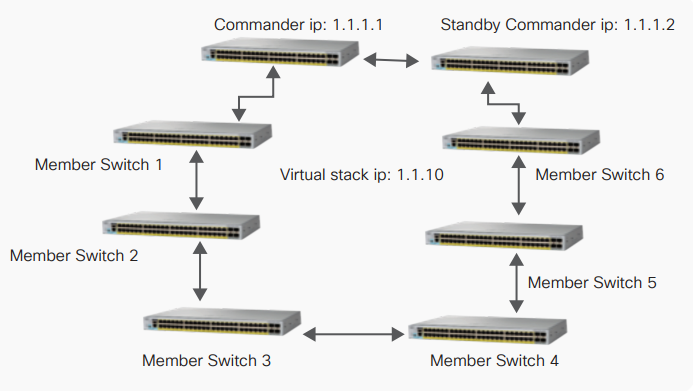
A switch can be configured as a standby commander for a cluster to make sure of continued manageability of the cluster switches in case a commander switch fails. The standby switch will take over only in a situation in which the commander switch fails. In such a case, the standby switch will assume the virtual stack address.
Configuration for high availability is similar to that of HSRP, including the timers and priority. (See Figure1.)
Figure1. High availability on a virtual stack
Configure commander switch
On the commander switch, make sure that the switch has an IP address.
After configuring the IP address, similar to that of HSRP configuration, create a standby group and assign it the IP address as that of the virtual stack.
For the group created, make sure that the commander switch is configured with a higher priority than that of the standby commander switch.
commander_switch(config-if)#interface <commander switch

interface>

commander_switch(config-if)#ip address <ip address>

<netmask>

commander_switch(config-if)#standby <group> ip <virtual

stack ip>

commander_switch(config-if)#standby <group> priority

<value>

commander_switch(config-if)#standby <group> preempt

commander_switch(config-if)#standby <group> name

<groupname>

commander_switch(config-if)#end

commander_switch(config)#cluster standby-group <groupname>

Catalyst2960L-2009(config)#interface Vlan 1

Catalyst2960L-2009(config-if)#ip address 1.1.1.1

255.255.255.0

Catalyst2960L-2009(config-if)#standby 10 ip 1.1.1.10

Catalyst2960L-2009(config-if)#standby 10 priority 110

Catalyst2960L-2009(config-if)#standby 10 preempt

Catalyst2960L-2009(config-if)#standby 10 name stand

Catalyst2960L-2009(config-if)#end

Catalyst2960L-2009(config)#cluster standby-group stand
Configure standby commander switch
Similar to the configuration of the commander switch, configure the standby commander switch.
standby_switch(config-if)#interface <standby commander

switch interface>

standby_switch(config-if)#ip address <ip address> <netmask>

standby_switch(config-if)#standby <group> ip <virtual stack

ip>

standby_switch(config-if)#standby <group> priority <value>

standby_switch(config-if)#standby <group> name <groupname>

standby_switch(config-if)#end

Catalyst2960L(config)#interface Vlan1

Catalyst2960L(config-if)# ip address 1.1.1.2 255.255.255.0

Catalyst2960L(config-if)# standby 10 ip 1.1.1.10

Catalyst2960L(config-if)# standby 10 priority 109

Catalyst2960L(config-if)# standby 10 name stand

Catalyst2960L(config-if)#end
Verify high-availability configuration
On the commander switch, execute the “show cluster” and “show cluster member” commands and verify that the standby commander is configured.
commander_switch#show cluster

Command switch for cluster “CorporateCluster”

 Total number of members: 2

 Status: 0 members are unreachable

 Time since last status change: 0 days, 1 hours, 4 minutes

 Redundancy: Enabled

 Active Command Switch: Member 15

 Standby Command Switch: Member 2

 Standby Group: stand

 Standby Group Number: 10

 Heartbeat interval: 8

 Heartbeat hold-time: 80

 Extended discovery hop count: 3

commander_switch#show cluster members

 |---Upstream---|

SN MAC Address Name PortIf FEC Hops SN PortIf FEC State

2 2xx2.6xx6.8xx0 Catalyst2960 Gi7/0/12 1 15 Gi0/12 Up (Standby)

15 cxx4.a0xx.xxxx Catalyst2960 0 Up (Cmdr)
On the standby commander, execute the “show cluster” command to verify.
standby_switch#show cluster

Member switch for cluster “CorporateCluster”

 Member number: 2 (Standby command

switch)

 Management IP address: 1.1.1.10

 Command switch mac address: cxx4.a0xx.xxxx

 Heartbeat interval: 8

 Heartbeat hold-time: 80
Implementation considerations for virtual stacking
Domain hop count
Cisco Catalyst 2960-L switches support a maximum of eight switches in single virtual domain, and every switch can be configured to only be a part of a single domain.
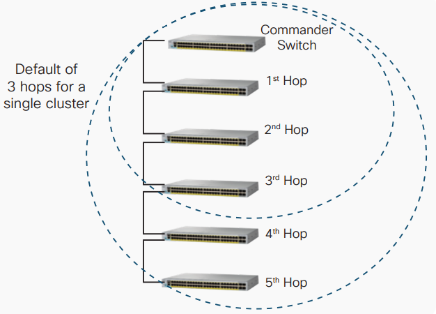
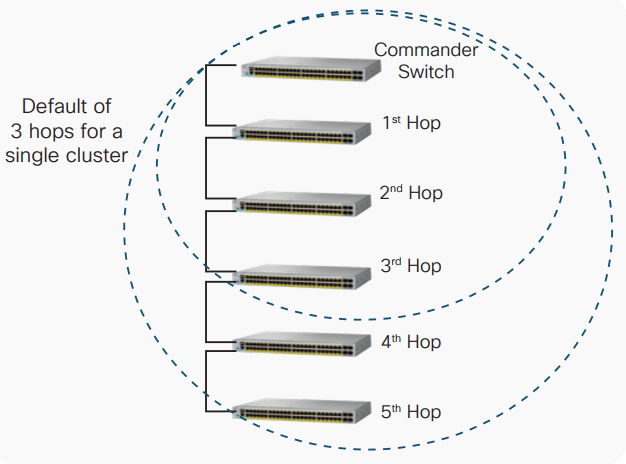
Member switches by default can be only three hops away from the commander switch. This means the commander switch will discover only the switches connected in a ring or star topology if they are up to three cluster-enabled switches away. (See Figure2.) This value can be changed to a maximum of seven hops through this configuration:
commander_switch(config-if)#cluster discovery hop-count
Figure2. Virtual domain member three hops away are detected by default from commander
Switches interconnected using non-cluster-capable Cisco switches cannot be added to the same cluster group. However, switches interconnected through a hub that is not capable of using Cisco Discovery Protocol can be discovered by the commander switch.
Stack management through different VLAN
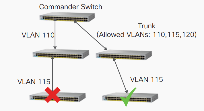
The commander switch can discover and manage switches in different VLANs. However, the member switch must have at least one VLAN in common with the commander switch. (See Figure3.)
Figure3. Switches should have at least one VLAN in common throughout all hops
The virtual stacking technology provides an easy and effective way for administrators to maintain and manage Cisco Catalyst 2960-L switches without having to invest in any additional hardware or compromise on network performance.
Reference from https://www.cisco.com/c/dam/en/us/products/collateral/switches/catalyst-2960-x-series-switches/white-paper-c11-739615.pdf
More Related
Cisco Catalyst 2960-L Series Switches FAQ
How to Configure a Virtual Stack on Cisco Catalyst 2960-L?
Virtual Stacking and Associated Terminologies
FlexStack vs. Virtual Stacking
How to Stack Cisco Catalyst 2960-X or 2960-XR Series Switches?
C2960X-STACK vs. C2960X-FIBER-STK vs. C2960X-HYBRID-STK

Expertise Builds Trust
20+ Years • 200+ Countries • 21500+ Customers/Projects
CCIE · JNCIE · NSE7 · ACDX · HPE Master ASE · Dell Server/AI Expert
