
In the last article, we discussed the Types of Cisco Switches for Your Campus Networks & Data Centers, the comparison between the Layer 2 and Layer 3 switches, Layer 3 (Multilayer) Switch Operation and Layer 2 Switch Operation. So in the following part we will say something about the Cisco switching methods.
The term Cisco switching methods describes the route processor behavior found on Cisco IOS routers. Because multilayer switches are capable of routing and, in fact, contain a routing process, a review of these concepts is necessary.
A Cisco IOS-based router uses one of three methods to forward packets: process switching, fast switching, and Cisco Express Forwarding (CEF). Recall from your study of routers that process switching is the slowest form of routing because the router processor must route and rewrite using software. Because speed and the number of cores limit the route processor, this method does not scale. The second method, fast switching, is a faster method by which the first packet in a flow is routed and rewritten by a route processor using software, and each subsequent packet is then handled by hardware. The CEF method uses hardware forwarding tables for most common traffic flows, with only a few exceptions. If you use CEF, the route processor spends its cycles mostly on other tasks.
The architecture of the Cisco Catalyst and Nexus switches both focus primarily on the Cisco router equivalents of CEF. The absolute last-resort switching method for Cisco Catalyst or Nexus switches is process switching. The route processors of these switches were never designed to switch or route packets, and by doing so, this will have an adverse effect on performance. Fortunately, the default behavior of these switches is to use fast switching or CEF, and process switching occurs only when necessary.
With Cisco Catalyst switching terminology, fast switching is referred to as route caching, and the application of CEF with distributed hardware forwarding is referred to as topology-based switching.
As a review, the following list summarizes route caching and topology-based forwarding on Cisco Catalyst switches:
- Route caching: Also known as flow-based or demand-based switching, route caching describes a Layer 3 route cache that is built within the hardware functions as the switch detects traffic flow into the switch. This method is functionally equivalent to fast switching in Cisco IOS Software.
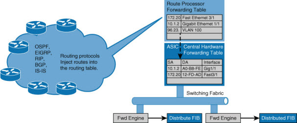
- Topology-based switching: Information from the routing table is used to populate the route cache, regardless of traffic flow. The populated route cache is the FIB, and CEF is the facility that builds the FIB. This method is functionally equivalent to CEF in Cisco IOS Software.
Route Caching
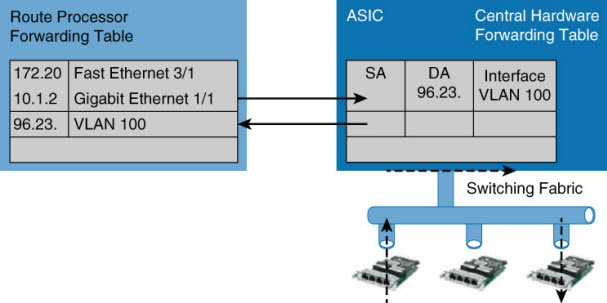
Route caching is the fast switching equivalent in Cisco Catalyst switches. For route caching to operate, the destination MAC address of an incoming frame must be that of a switch interface with Layer 3 capabilities. The first packet in a stream is switched in software by the route processor, because no cache entry exists yet for the new flow. The forwarding decision that is made by the route processor is then programmed into a cache table (the hardware forwarding table), and all subsequent packets in the flow are switched in the hardware, commonly referred to as using application-specific interface circuits (ASICs). Entries are created only in the hardware forwarding table as the switch detects new traffic flows, and entries will time out after they have been unused for a period of time.
Because entries are created only in the hardware cache as flows are detected by the switch, route caching will always forward at least one packet in a flow using software.
Route caching carries many other names, such as NetfFow LAN switching, flow-based or demand-based switching, and route once, switch many.
Route Caching
Topology-Based Switching
Topology-based switching is the CEF equivalent feature of Cisco Catalyst switches. Topology-based switching is ideal for Layer 3 switching over route caching because it offers the best performance and scalability. Fortunately, all Cisco Catalyst switches capable of Layer 3 routing leverage topology-based switching / CEF. For the purpose of CCNP Switch, focus primarily on the benefits and operation of topology-based switching.
CEF uses information in the routing table to populate a route cache (known as an FIB), without traffic flows being necessary to initiate the caching process. Because this hardware FIB exists regardless of traffic flow, assuming that a destination address has a route in the routing table, all packets that are part of a flow will be forwarded by the hardware. The FIB even handles the first packet of a flow.
Topology-Based Switching
In addition, CEF adds enhanced support for parallel paths and thus optimizes load balancing at the IP layer. In most current-generation Catalyst switches, such as the Catalyst 4500 and 6800, CEF supports both load balancing based on source IP address and destination IP address combination and source and destination IP plus TCP/UDP port number.
NOTE: The load-balancing options and default behavior varies between different Catalyst switch models and software versions. Consult Cisco.com for the particular Catalyst switch you have in question for supported load-balancing methods and default configurations.
CEF load-balancing schemes allow for Layer 3 switches to use multiple paths to achieve load sharing. Packets for a given source-destination host pair are guaranteed to take the same path, even if multiple paths are available. This ensures that packets for a given host pair arrive in order, which in some cases may be the desired behavior with legacy applications.
Moreover, load balancing based only on source and destination IP address has a few shortcomings. Because this load-balancing method always selects the same path for a given host pair, a heavily used source-destination pair, such as a firewall to web server, might not leverage all available links. In other words, the behavior of this load-balancing scheme may “polarize” the traffic by using only one path for a given host pair, thus effectively negating the load-balancing benefit of the multiple paths for that particular host pair.
So, optimal use of any load-balancing scheme depends on the statistical distribution of traffic because source and destination IP load sharing becomes more effective as the number of source-destination IP pairs increases. In an environment where there is a broad distribution of traffic among host pairs, polarization is of minimal concern. However, in an environment where the data flow between a small number of host pairs creates a disproportionate percentage of the packets traversing the network, polarization can become a serious problem.
A popular alternative that is now the default behavior in new Catalyst switches is load balancing based on source and destination IP to include TCP/UDP port numbers. The more additional factors added to the load-balancing scheme, the less likely polarization will exist.
Cisco Catalyst supports additional load-balancing methods and features by which to tune load balancing based on hardware model and software version. Consult Cisco.com for such configuration optimizations if necessary.
Hardware Forward Details
The actual Layer 3 switching of packets occurs at two possible different locations on Catalyst switches. These possible locations are in a centralized manner, such as on a supervisor module, or in distributed fashion, where switching occurs on individual line modules. These methods are referred to as centralized switching and distributed switching, respectively.
The Catalyst 6500 was a perfect example where there was an option to centralize switch everything on the supervisor or place specific hardware versions of line modules in the chassis to gain distributed switching capability.
The benefits of centralized switching include lower hardware cost and lower complexity. For scaling and large enterprise core networks, distributed switching is optimal. Most small form-factor switches leverage centralized switching.
NOTE: Some small form-factor switches may leverage a switch-on-chip (SOC) concept, where the entire intelligence and processing of the switch happens on a single low-cost ASIC. This practice has now become an industry standard for low-feature and low-cost switches and is found on specific fixed-port Cisco Catalyst and Nexus switches. In addition, newer generation modular switches such as the Nexus 9000 may leverage SOC in a hybrid capacity, whereas line modules may contain their own SOC and leverage distributed switching concepts.
In conclusion, the subsections of this chapter pertaining to switching methods and hardware forwarding included many specific details about routing and switching operations on Cisco switches. Among all the lengthy explanations and details, conclude this section with the following concepts:
- The control plane (CPU/route processor) of a Cisco Catalyst was never designed to route or switch frames. The control plane is intended only to populate hardware tables with routing information and maintain routing protocols. The control plane may route frames in a few exception conditions.
- Medium- to high-end Cisco Catalyst switches were designed based on the distributing forward model to scale to demands of campus and data center networks.
- Cisco Catalyst switches leverage CEF (topology-based switching) for routing of frames as a means to implement a distributing hardware forwarding model.
- Cisco Catalyst switches use either a centralized method or a distributed line module method of hardware forwarding, depending on specific platform model and configuration.
Study Tips
- The show mac address-table command displays the Layer 2 forwarding table of a Cisco switch.
- Layer 2 switches forward traffic based on the destination MAC address of a frame.
- Campus network designs are still built upon the hierarchical model, where end devices connect to the access layer, the distribution layer aggregates the access layer, and the core aggregates the entire enterprise network.
- Cisco switches leverage CEF (topology-based switching) for Layer 3 forwarding.
In this article and about the Cisco Catalyst Switches for Campus Networks & Nexus Switches for Data Centers we briefly talked about campus networks, including the hierarchical model, benefits of Layer 3 routing the access, Cisco switches, and some hardware details related to Cisco Catalyst switches. The information we shared can be summarized as follows:
- Flat Layer 2 networks are extremely limited in scale and in most cases will only scale to 10 to 20 end users before adverse conditions may occur.
- Despite its age, the hierarchical model continues to be a key design fundamental of any network design, including campus network designs.
- The hierarchical model consists of an access, distribution, and core layer, thus allowing for scalability and growth of a campus network in a seamless manner.
- The different models of Cisco Catalyst switches provide for a range of capabilities depending on need and placement within the hierarchical model.
- Cisco Catalyst switches leverage CAM for Layer 2 forwarding tables and TCAM for Layer 3 forwarding tables to achieve line-rate performance.
- Cisco Catalyst switches leverage CEF (topology-based switching) for routing, utilizing a distributed hardware forwarding model that is centralized or distributed per line card.
This Article was written by Richard Froom, Erum Frahim From https://www.ciscopress.com/articles/article.asp?p=2348265&seqNum=2
More Related…
Cisco Catalyst Switches for Campus Networks & Nexus Switches for Data Centers
Compare Cisco Products and Solutions
All about Cisco’s Stacking Switches
Qs Help You Know Cisco Catalyst Instant Access a Lot
Catalyst 6800ia Switches, the Relationship with Catalyst 6500/6800


