
We talked about Cisco switches and related technical topics a lot before. It’s not easy to select the very Cisco switches for all sizes of networks, such as the complicated campus networks and data center. You know that switches are the fundamental interconnect component of the campus network. Cisco is very famous for offering a variety of switches specifically designed for different functions. Yes, Cisco designed different Catalyst switches for campus networks and Nexus switches for data centers. Now, in this article, we will mainly discuss the Cisco Catalyst switches.
Firstly, let’s have a look at the current recommended Catalyst switches.
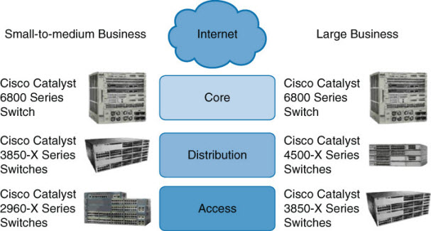
Two types of Cisco switches: fixed configuration and modular switches.
With fixed configuration switches, you cannot swap or add another module, like you can with a modular switch. In enterprise access layers, you will find fixed configuration switches, like the Cisco Catalyst, 2960-X series. It offers a wide range of deployments.
In the enterprise distribution layer, you will find either fixed or modular switches depending on campus network requirements. An example of a modular switch that can be found in the distribution layer is the Cisco Catalyst 3850-X series. This series of switches allows you to select different network modules (Ethernet or fiber optic) and redundant power supply modules. In small businesses without a distribution layer, the Cisco 3850-X can be found in the core layer. In large enterprise networks, you might find 3850-X in the access layer in cases where high redundancy and full Layer 3 functionality at the access layer are requirements.
In the enterprise core layer, you will often find modular switches such as the Cisco Catalyst 6500 or the Catalyst 6800 series. With the 6800 switch, nearly every component, including the route processing/supervisor module and Ethernet models to power supplies) is individually installed in a chassis. This individualization allows for customization and high-availability options when necessary.
If you have a network where there is a lot of traffic, you have the option to leverage the Cisco Catalyst 4500-X series switches into the distribution layer. The Catalyst 4500-X supports supervisor/route process redundancy and supports 10 Gigabit Ethernet.
All switches within the 2960-X, 3850-X, 4500-X, and 6800-X series are managed. This means that you can configure an IP address on the device. By having a management IP address, you can connect to the device using Secure Shell (SSH) or Telnet and change device settings. An unmanaged switch is only appropriate for a home or very small business environment. It is highly recommended not to use an unmanaged switch in any campus network.
Layer 2 vs. Multilayer Switches
A Layer 2 Ethernet switch operates at the Data Link Layer of the OSI model. These types of switches make decisions about forwarding frames based on the destination MAC addresses found within the frame.
Recalling basic networking: A switch collision domain is only port to port because each switch port and its associated end device is its own collision domain. Because there is no contention on the media, all hosts can operate in full-duplex mode, which means that they can receive and transmit data at the same time. The concept of half duplex is legacy and applies only to hubs and older 10/100-Mbps switches, because 1 Gbps operates by default at full duplex.
When a switch receives in store-n-forward mode, the frame is checked for errors, and frames with a valid cyclic redundancy check (CRC) are regenerated and transmitted. Some models of switches, mostly Nexus switches, opt to switch frames based only on reading the Layer 2 information and bypassing the CRC check. This bypass, referred to as cut-through switching, lowers the latency of the frame transmission as the entire frame is not stored before transmission to another port. Lower switching latency is beneficial for low-latency applications such as algorithm trading programs found in the data center. The assumption is that the end device network interface card (NIC) or an upper-level protocol will eventually discard the bad frame. Most Catalyst switches are store-n-forward.
MAC Address Forwarding
To figure out where a frame must be sent, the switch will look up its MAC address table. This information can be told to the switch or it can learn it automatically. The switch listens to incoming frames and checks the source MAC addresses. If the address is not in the table already, the MAC address, switch port, and VLAN will then get recorded in the forwarding table. The forwarding table is also called the CAM table.
What happens if the destination MAC address of the frame is unknown to the switch? The switch then forwards the frame through all ports within a VLAN except the port the frame was received on. This is known as unknown unicast flooding. Broadcast and multicast traffic is destined for multiple destinations, so it will get flooded by default.
Referring to the following info graphic, in the first example, the switch receives a frame on port 1. The destination MAC address for the frame is 0000.0000.5555. The switch will look up its forwarding table and figure out that MAC address 0000.0000.5555 is recorded on port 5. The switch will then forward the frame through port 5.
Layer 2 Switching Operation: MAC Address Forwarding
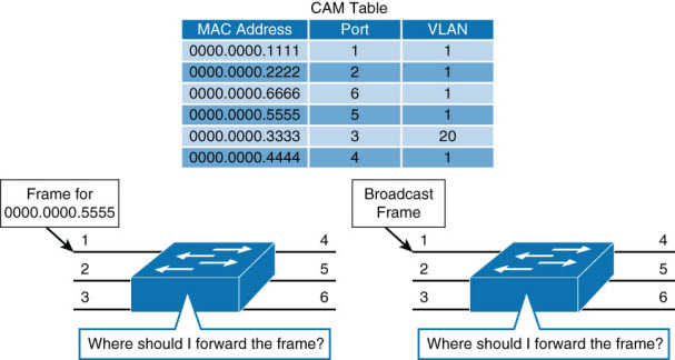
In the second example, the switch receives a broadcast frame on port 1. The switch will forward the frame through all ports that are within the same VLAN except port 1. The frame was received on port 1, which is in VLAN 1; therefore, the frame is forwarded through all ports on the switch that belong to VLAN 1 (all ports except port 3).
The next subsection discusses Layer 2 switch operation from a mechanics point of view.
Layer 2 Switch Operation
When a switch receives a frame, it places the frame into an ingress queue. A port can have multiple ingress queues, and typically these queues are used to service frames differently (for example, apply quality of service [QoS]). From a simplified viewpoint, when the switch selects a frame from a queue to transmit, the switches need to answer a few questions:
- Where should the frame be forwarded?
- Are there restrictions preventing the forwarding of the frame?
- Is there any prioritization or marking that needs to be applied to the frame?
Decisions about these three questions are answered, respectively, as illustrated and described in the list that follows.
Layer 2 Switch Operation: Mechanics
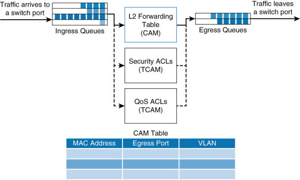
- Layer 2 forwarding table: The Layer 2 forwarding table, also called the MAC table, contains information about where to forward the frame. Specifically, it contains MAC addresses and destination ports. The switches reference the destination MAC address of the incoming frame in the MAC table and forward the frames to the destination ports specified in the table. If the MAC address is not found, the frame is flooded through all ports in the same VLAN.
- ACLs: Access control lists (ACLs) do not only apply to routers. Switches can also apply ACLs based on MAC and IP addresses. Generally only higher-end switches support ACLs based on both MAC and IP addresses, whereas Layer 2 switches support ACLs only with MAC addresses.
- QoS: Incoming frames can be classified according to QoS parameters. Traffic can then be marked, prioritized, or rate-limited.
Switches use specialized hardware to house the MAC table, ACL lookup data, and QoS lookup data. For the MAC table, switches use content-addressable memory (CAM), whereas the ACL and QoS tables are housed in ternary content-addressable memory (TCAM). Both CAM and TCAM are extremely fast access and allow for line-rate switching performance. CAM supports only two results: 0 or 1. Therefore, CAM is useful for Layer 2 forwarding tables.
TCAM provides three results: 0, 1, and don’t care. TCAM is most useful for building tables for searching on longest matches, such as IP routing tables organized by IP prefixes. The TCAM table stores ACL, QoS, and other information generally associated with upper-layer processing. As a result of using TCAM, applying ACLs does not affect the performance of the switch.
Layer 3 (Multilayer) Switch Operation
Multilayer switches not only perform Layer 2 switching but also forward frames based on Layer 3 and 4 information. Multilayer switches not only combine the functions of a switch and a router but also add a flow cache component.
Multilayer switches apply the same behavior as Layer 2 switches but add an additional parallel lookup for how to route a packet.
Multilayer Switch Operation

The associated table for Layer 3 lookups is called a FIB table. The FIB table contains not only egress ports and VLAN information but also MAC rewrite information. The ACL and QoS parallel lookups happen the same as Layer 2 switches, except there may be additional support for Layer 3 ACLs and QoS prioritization.
For example, a Layer 2 switch may only be able to apply to rate-limiting frames based on source or destination MAC addresses, whereas a multilayer switch generally supports rate-limiting frames on IP/MAC addresses.
Unfortunately, different models of Cisco switches support different capabilities, and some Layer 2-only switches actually support Layer 3 ACLs and QoS lookups. It is best to consult the product documentation at Cisco.com for clear information about what your switch supports. For the purpose of CCNP Switch and the context of this book, Layer 2 switches support ACLs and QoS based on MAC addresses, whereas Layer 3 switches support ACLs and QoS based on IP or MAC addresses.
Useful Commands for Viewing and Editing Catalyst Switch MAC Address Tables
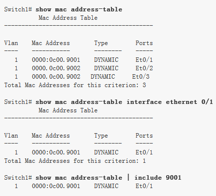
There is one command for viewing the Layer 2 forwarding table on Catalyst and Nexus switches: show mac address-table. The table has many optional parameters to narrow the output to a more manageable result in large networks. The full command options are as follows: show mac-address-table [aging-time | count | dynamic | static] [address hw-addr] [interface interface-id] [vlan vlan-id] [ | {begin | exclude | include} expression].
Sample Uses of the Command and Several Useful Optional Uses
Layer 2 Forwarding Table
Frame Rewrite
From your CCNA studies, you know that many fields of a packet must be rewritten when the packets are routed between subnets. These fields include both source and destination MAC addresses, the IP header checksum, the TTL (Time-to-Live), and the trailer checksum (Ethernet CRC). See Chapter 1, “Fundamentals Review,” for an example.
Distributed Hardware Forwarding
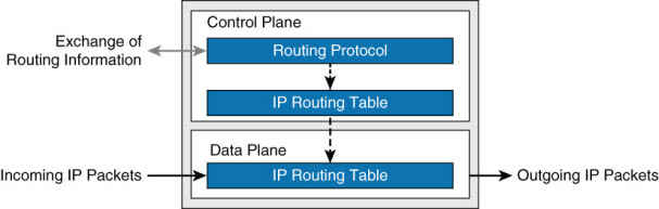
Network devices contain at least three planes of operation:
- Management plane
- Control plane
- Forwarding plane
The management plane is responsible for the network management, such as SSH access and SNMP, and may operate over an out-of-band (OOB) port. The control plane is responsible for protocols and routing decisions, and the forwarding plane is responsible for the actual routing (or switching) of most packets.
Multilayer switches must achieve high performance at line rate across a large number of ports. To do so, multilayer switches deploy independent control and forwarding planes. In this manner, the control plane will program the forwarding plane on how to route packets. Multilayer switches may also employ multiple forwarding planes. For example, a Catalyst 6800 uses forwarding planes on each line module, with a central control plane on the supervisor module.
To continue the example of the Catalyst 6800, each line module includes a microcoded processor that handles all packet forwarding. For the control plane on the supervisor to communicate with the line module, a control layer communication protocol exists.
Distributed Hardware Forwarding
The main functions of this control layer protocol between the control plane and the forwarding plane are as follows:
- Managing the internal data and control circuits for the packet-forwarding and control functions
- Extracting the other routing and packet-forwarding-related control information from the Layer 2 and Layer 3 bridging and routing protocols and the configuration data, and then conveying the information to the interface module for control of the data path
- Collecting the data path information, such as traffic statistics, from the interface module to the route processor
- Handling certain data packets that are sent from the Ethernet interface modules to the route processor (for example, DCHP requests, broadcast packets, routing protocol packets)
Original Article From https://www.ciscopress.com/articles/article.asp?p=2348265&seqNum=2
More Related…
Compare Cisco Products and Solutions
All about Cisco’s Stacking Switches
Qs Help You Know Cisco Catalyst Instant Access a Lot
Catalyst 6800ia Switches, the Relationship with Catalyst 6500/6800
Why We Need Multigigabit Networks Today?
Cisco 4510E or Catalyst 6800ia Switch

Expertise Builds Trust
20+ Years • 200+ Countries • 21500+ Customers/Projects
CCIE · JNCIE · NSE7 · ACDX · HPE Master ASE · Dell Server/AI Expert
