Cisco StackPower Technology is so cool that it can aggregates all of the available power in a stack of switches and manages it as one common power pool for the entire stack, sharing the power where needed. You can configure up to four switches in a stack with the special connector at the back of the switch using the Cisco StackPower cable, which is different from the Cisco StackWise 480. (This technology is not supported on the Cisco Catalyst3650; it is supported only on the Catalyst 3850.)
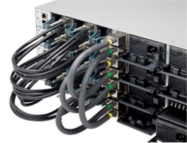
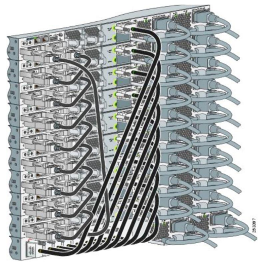
Cisco StackWise 480 and Cisco StackPower Connectors
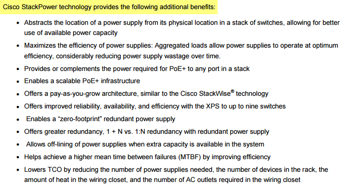
The key aspect to Cisco StackPower technology is the way power is supplied and distributed to a switch in the stack. A switch requires that power be provided at different voltage levels, such as 5 VDC and 48 VDC, and a traditional power supply provides those voltages. These requirements make the power supply more complex, and this complexity affects efficiency.
Cisco StackPower technology implies a new approach to power-supply design and power distribution in a switch, but its effects are most significant in a stack of switches.
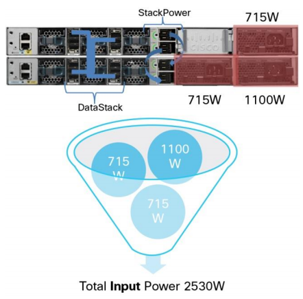
The Cisco Catalyst 3850 Series Switches are designed for power supplies that provide a single power voltage. This approach simplifies the power-supply design and allows aggregation of power, from power supplies in a single switch and across switches in a power stack. Cisco StackPower technology creates a pool of power that shares a common load consisting of all the switches in the power stack. This capability to manage power as a shared resource is unique to a stack of switches that can operate as a single unit. Therefore, this technology is available only on the Catalyst 3850 Switches.
Note that all power available in the power stack is combined into one single large pool of power, and the stack becomes a large single load to the power pool.
Cisco StackPower Technology: One Power Pool, One Load
A surplus of power in a power stack enables features such as zero-footprint redundant power supply and 1 + N redundancy instead of the classic 1:N redundancy with dedicated external redundant power supply.
Redundancy with Cisco StackPower technology is better because the redundant power is already in line (1 + N), as opposed to being switched from one source to another as in a classic redundant power supply (1:N). The 1 + N redundancies are less susceptible to problems because the power is already available in line.
Cisco StackPower Operation
Switches deployed in a power stack discover each other and exchange messages to figure out how much power is available in the stack (power budget), to set priorities (or use default priority values), and to start booting Cisco IOS Software on all switches, depending upon the power budget available in the stack.
The boot-up sequence of events is as follows:
- Switches are interconnected in a ring topology and power is applied.
- All switches power up their Cisco StackPower infrastructure.
- All switches participate in the power stack and exchange discovery packets and information messages regarding power resources and priorities.
- The total budget in the power stack is discovered.
- The power stack reserves 30W in case a new member is dynamically added to the stack. This amount is reserved once per stack, not per switch (unless there is only one switch in the stack).
- Budgets are distributed based on total power budget, power-draw requirements, and switch priorities.
- Switches that receive an allocation of power proceed to boot the Cisco IOS XE Software.
- Switches that did not receive a power allocation will remain in the power stack without booting until more power is added to the power budget.
Power budget required is higher for Cisco StackPower operation. This higher budget allows each switch to budget enough power for the switch itself, to power a high-power network module (if present), and to power its downstream neighbor’s Cisco StackPower logic (multipoint control unit [MCU]), which is the minimum number of components in a switch to form a power stack without booting Cisco IOS XE Software.
Power Budget Requirements for Cisco Catalyst 3850 Switches
| Product ID | Power Budget Requirement |
| 24-Port 3850 Copper (Data/PoE/PoE+/UPoE), 12/24 Port 3850 Fiber SFP | 200W |
| 48-Port 3850 Copper (Data/PoE/PoE+/UPoE), 48 Port 3850 Fiber SFP+ | 280W |
| 12-Port 3850 Fiber SFP+ | 300W |
| 24-Port 3850 Fiber SFP+ | 410W |
| 48-Port 3850 mGig | 470W |
| 24-Port 3850 mGig | 520W |
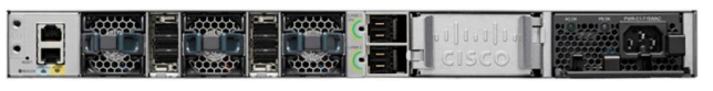
For example, a standalone Cisco Catalyst 3850-48P Switch (Figure 3) budgets 280W; this budget does not necessarily reflect the actual power consumption (refer to the data sheet for details).
Figure3. Cisco Catalyst 3850-48P
Adding a New Switch to a Power Stack
Cisco StackPower technology adds resiliency to the stack by reserving enough power to bring up the MCU of any Catalyst 3850 Series Switch. This reservation helps ensure that if and when a new switch without any power supplies is added to the power stack, it can join the power stack using the power that has been reserved for that purpose. This process guarantees the inclusion of a new switch in the power stack; if the power stack has enough power in the power pool, the technology will allocate power to the new switch to boot Cisco IOS XE Software.
Zero-Footprint Redundant Power Supply
The ability to provide redundancy without the need for an actual redundant power supply is called sero-footprint redundant power supply. The power stack discovers the members of the stack, aggregates power from all available sources in the stack, and subtracts from the power pool an amount of power equal to the largest power supply in the stack. It does not subtract the power supply itself, nor does it turn off any power supply.
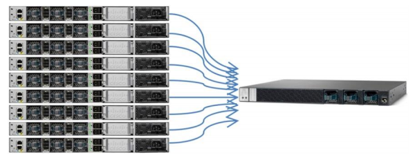
In the simplest example, a power stack is formed by using a special cable to connect switches to each other to form a closed ring, similar to the topology for a Cisco StackWise stack (Figure 4). Up to four switches can be part of a power stack in a ring topology, and up to nine switches can share power in a star topology by using an XPS (Figure 5). Current flows through the cables that form the power stack and feeds switches that need power or complements power requirements of other switches in the stack. It is a safe system with plenty of circuit breakers spread around the printed circuit board to cut off current to different components in the system or if needed, to the system itself.
Figure4. Ring Topology
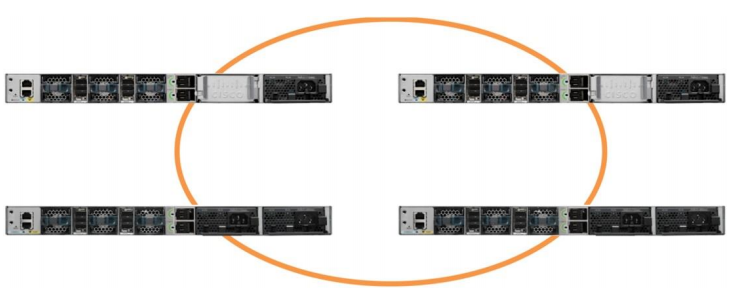
Figure5. Star Topology, Using an XPS
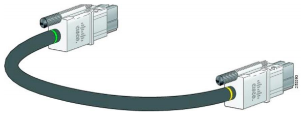
The Cisco StackPower cables are thick but flexible, and they carry power as well as a data signal to provide a communications channel among the switches in the power stack.
Cisco StackPower and XPS Cables
| Product ID | Description |
| CAB-SPWR-30CM | 30cm StackPower cable |
| CAB-SPWR-150CM | 150cm StackPower cable |
Cisco StackPower and XPS cables are keyed and have colored bands on the ends to help you understand what cable plugs into what switch or XPS.
The cable shown in Figure 6 connects a Catalyst 3850 Switch to another Catalyst 3850 Switch in a power stack or with an XPS. Cisco StackPower cables have color bands on the cable ends:
● The cable end with the green band can connect only to a Catalyst 3850 Switch.
● The cable end with the yellow band can connect to a Catalyst 3850 Switch or an XPS.
Figure6. Cisco StackPower Cable for Use with Catalyst 3850 Switches
Before connecting the switches in a power stack, follow these guidelines:
- A switch power stack can include a maximum of four switches in a ring topology and nine switches in a star topology with XPS.
- Size of the switch and any optional power-supply module: The 1100W power-supply module is 1.5 inches (3.81 cm) longer than the other modules, and with the attached cable retention clip, it extends 3 inches (7.62 cm) from the switch chassis. Stacking switches with the same power-supply modules together makes it easier to cable the switches.
- Length of cable: Depending on the configurations that you have, you might need different-size cables. If you do not specify the length of the Cisco StackPower cable, the 0.3-meter cable is supplied. If you need the 1.5-meter cable, you can order it from your Cisco supplier. For cable part numbers, refer to Table 2. The Cisco StackPower cabling configurations that follow provide examples of recommended configurations.
Figure7 shows a ring configuration using both of the supplied 0.3-meter Cisco StackPower cables and one 1.5-meter cable. In the examples that follow, the switches are stacked in a vertical rack or on a table.
Figure7. Cisco StackPower Ring Topology
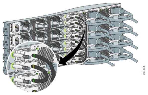
Figure8 shows nine switches connected in a star topology.
Figure8. Cisco StackPower Star Topology
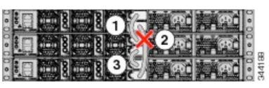
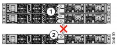
Figures9 and 10 show Cisco StackPower stacks of Catalyst 3850 Switches with failover conditions.
In Figure9, the Cisco StackPower cable 2 is faulty. Therefore, this stack does not provide redundancy.
Figure9. Example of a Cisco StackPower Stack with a Failover Condition
In Figure10, Cisco StackPower port B on the center switch has failed and this stack partitions into two stacks. The top two switches share power, and the bottom switch is now a separate stack.
Figure10. Example of a Partitioned Cisco StackPower Stack with a Failover Condition
The stackable* Cisco Catalyst 3850 Series Switches come with four power-supply options; you can use any of them on any switch in a stack and in any combination. Table3 lists these options.
Table3. Power-Supply Options for the Cisco Catalyst 3850 Series Switches
| Product ID | Description |
| C3KX-PWR-350WAC | 350W AC power supply |
| C3KX-PWR-715WAC | 715W AC power supply |
| C3KX-PWR-1100WAC | 1100W AC power supply |
| C3KX-PWR-440WDC | 440W DC power supply |
* Cisco Catalyst 3850 48XS Series Switches do not support stack capabilities and have different power supplies with different part numbers. This switch cannot share power with other Cisco Catalyst 3850 Switches.
The Cisco Catalyst 3850 Switches provide two slots for redundant power supplies, but only one supply is needed to run a single switch unless full PoE+ is deployed on a 48-port switch. In that case, the power requirement is about 1700W, which is more than the 1100W provided by the largest available power supply. If the switch is deployed within a Cisco StackPower stack, a second power supply might not be needed if the stack has extra power to meet the requirements of this switch, though the power-supply slot must be covered to maintain proper airflow.
You can mix the power-supply types either in a standalone switch or in a stack. That is, you can combine a 350W AC power supply (the default for a data-only switch) with a 715W or 1100 WAC power supply (the default in a full PoE switch) or with a 440 WDC power supply. An exception is the Cisco Catalyst 3850 48-port 10G SFP+ switch, which has different AC and DC power supplies. You cannot mix or reuse these power supplies with the other Cisco Catalyst 3850 Switches.
The following are some important concepts for Cisco StackPower technology:
● The Cisco StackPower feature is responsible for the negotiation and distribution of power from a common power pool among the switches participating in the power stack.
● The intelligent load shed is a mechanism that Cisco StackPower technology uses to decide what devices must power down when the available power drops below the allocated power levels. A priority scheme is used to set different levels that become useful when:
◦ Load shedding in case the power budget falls below the allocated power levels
◦ Initial allocation of power to boot up into Cisco IOS XE Software: You can change priorities for powered devices and switches to values other than the preconfigured default values.
● Physical placement of power supplies in a switch is independent of the power required for that switch.
● A switch may not be allowed to boot up with Cisco IOS XE Software if all available power in the common pool has already been allocated. But this switch continues to participate in the power stack while waiting for more power to become available to allow it to boot.
● The power stack reports all of the Cisco StackPower information to the stack master; therefore, configuring a power stack that spans multiple data stacks is not recommended (refer to the “Best Practices” section).
…More use case for the Cisco StackPower feature you can read the full Cisco StackPower Technology-Efficient Use of Power White Paper: https://www.cisco.com/c/en/us/products/collateral/switches/catalyst-3850-series-switches/white-paper-c11-737746.html
More Related Topics
Cisco StackPower: Highly Available Power
Cisco Catalyst 3850 Models Comparison
All about Cisco’s Stacking Switches
Cisco Switch Stacking Using a Couple of Cisco Catalyst 3650
Cisco Catalyst 3850 Series- the Industry’s first Fixed, Stackable GE Switch
