
Huawei CE6800 (Huawei CloudEngine 6800 series) belongs to the family of Huawei Switches for Data Processing Centers. CE6800 series switches were designed for data centers and high-end campus networks.

The CE6800 hardware has an advanced architectural design with 40GE uplink ports and the industry’s highest density of 10GE access ports. Using the Huawei VRP8 software platform, CE6800 switches provide extensive data center service features and high stacking capability.
In addition, the airflow direction (front-to-back or back-to-front) can be changed.
CE6800 switches can work with CE12800 switches to build an elastic, virtualized, high-quality fabric that meets the requirements of cloud-computing data centers.
CE6800 switches provide high-density 10GE access to help enterprises and carriers build a scalable data center network platform in the cloud computing era. They can also be used as aggregation or core switches for enterprise campus networks.
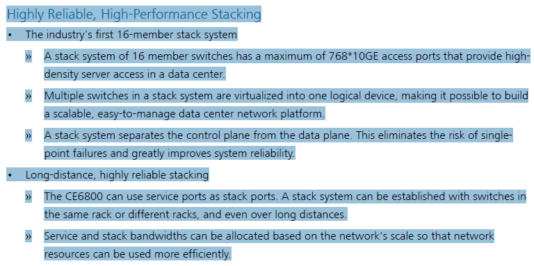
The Huawei CE6800 Series features the Highly Reliable, High-Performance Stacking.
In the following part, we will share someone’s experience of configuring two Huawei CE6851 Switches as TOR devises to connect servers. Let’s take a look.
“How to configure two Huawei CE6851 switches as TOR devises to connect servers?” The most suitable solution for servers access is M-LAG which is supported by CE6800 switches. But in this particular case I have special requirements from software engineer (who is deploying OpenStack) to place each of server’s physical interface in a different virtual network. So I decide to use iStack technology.
The stack setup for CE6800 is very similar to configuration for S6700, but not the same. There’re some nuances.
Stack Establishing Methods
We have two options to establish the stack:
- configure software and then connect stack cables
- connect stack cables and then configure software
Second method is applicable for remote configuration and requires a few more action. Because I have direct access to the equipment first option is more suitable for me.
iStack Configuration
For stack setup we must perform following actions:
- Meet software and hardware requirements
- Define a stack member ID
- Set a stack member priority
- Configure a stack domain ID
- Create stack-interfaces
- Add physical ports to stack-interfaces
- Check configuration
- Save configuration
- Power off switches
- Connect physical cables
- Power on switches
S6800 iStack software and hardware requirements
Stack function is supported by V100R005C10 and later versions of VRP.
We can use for stacking any of 10G or 40G physical interfaces. In this project two QSFP direct-attach cables are available for stacking purpose. So I use two 40G ports in accordance with the scheme at the top of this article.
Defining a stack member ID
If you look at interface numbers on S6800 we will see three digits: 40GE 1/0/1
First digital is stack member ШВ. By default it is set to 1. Switches joined to a stack must have different member ID, so we able to distinguish ports of different devices. They say master switch automatically change ID of other stack members to different numbers. I prefer set the member ID manually. Let it remain 1 for SW-A and change to 2 for SW-B:
[SW-B]stack

[SW-B-stack]stack member 1 renumber 2
Changes will take place after switch reboot. The reboot should be done right now.
Setting a stack member priority
A stack needs a master. It is the switch with higher priority or in a case with equal priority – with lowest MAC.
For different reason I wand SW-A gets master role. So we need change its priority from default 100 to some higher value (maximum is 255)
Switch A:
[SW-A]stack

[SW-A-stack]stack member 1 priority 255
Configuring a stack domain ID
Presence of the domain ID is key difference from S6700 iStack. Domain ID must match on all stack member switches. I like number 8, so I will use it for domain identification.
Switch A:
[SW-A]stack

[SW-A-stack]stack member 1 domain 8
Switch B:
[SW-B]stack

[SW-B-stack]stack member 2 domain 8
Creating stack-interfaces and iStack topology
Stack-interface is a kind of logical interfaces. Switch can have one or two stack-interfaces. Each stack-interface can contain no more than 4 physical interfaces. The number of stack-interfaces is defined by the topology we use.
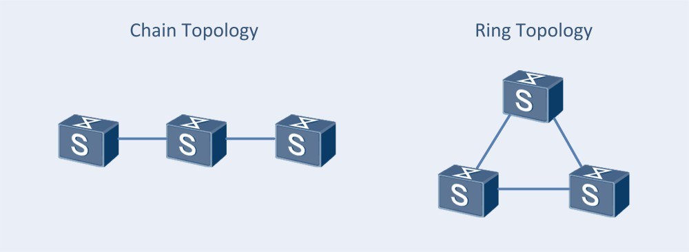
A chain topology is suitable when switches are far from one another and a ring topology is difficult to deploy. By default I use ring topology which has more reliability and link utilization.
In accordance with this we will configure two stack-interfaces with one physical interface in each.
Switch A:
[SW-A]interface stack-port 1/1

[SW-A-stack-port1/1]quite

[SW-A]interface stack-port 1/2

[SW-A-stack-port1/2]quite
Switch B:
[SW-B]interface stack-port 2/1

[SW-B-stack-port2/1]quite

[SW-B]interface stack-port 2/2

[SW-B-stack-port2/2]quite
Adding physical ports to stack-interfaces
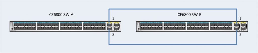
Remember that stack-port 1 on one switch must be linked to stack-port 2 on another device. And vice versa.
As you can see in the picture at the top of the article, I have connected SW-A 40GE 0/1 and 40GE 0/2 to SW-B 40GE 0/1 and 40GE 0/2 respectively. So on SW-A we will add 40GE 0/1 to stack-port 1 and 40GE 0/2 to stack-port 2. Herewith on SW-B we must add 40GE 0/1 to stack-port 2 and 40GE 0/2 to stack-port 1.
Switch A:
[SW-A]interface stack-port 1/1

[SW-A-stack-port1/1]port member-group interface 40 1/0/1

[SW-A-stack-port1/2]quite

[SW-A]interface stack-port 1/1

[SW-A-stack-port1/1]port member-group interface 40 1/0/2

[SW-A-stack-port1/2]quite
Switch B:
[SW-B]interface stack-port 2/1

[SW-B-stack-port2/1]port member-group interface 40 2/0/2

[SW-B-stack-port2/2]quite

[SW-B]interface stack-port 2/1

[SW-B-stack-port2/1]port member-group interface 40 2/0/1

[SW-B-stack-port2/2]quite
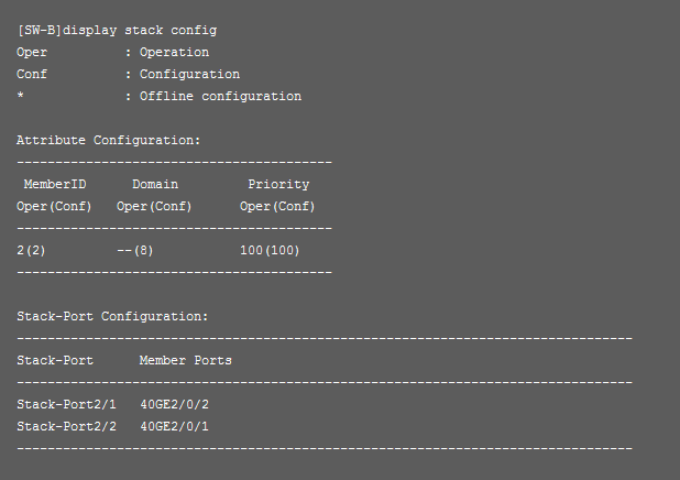
Checking and the configuration
We’ve performed all necessary configuration. Let’s check final state:
SW-A:
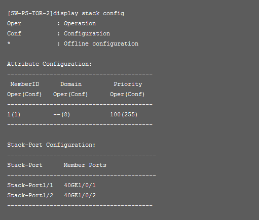
SW-B:
Saving the configuration
Huawei S5700 and S6700 switches save iStack configuration automatically. But when you work with CE5800 and CE6800 you need to save configuration manually.
So have implement command save on both switches.
Now all have correctly done. Power off!
9,10. Power off and cables connecting.
I power off my switches and connect cables for stacking according the scheme.
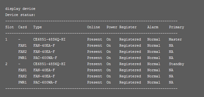
Power on and checking the status of the stack.
If everything has been done correctly after reboot you will get one logical device.
…
The Original Article From https://dis-this.com/huawei-ce6800-istack/
More Related…
Huawei Fixed Switches Overview
Decode the Huawei S5700 Switches
Huawei S5700-EI in Network–Sample Deployments
The Role of Huawei S5700 Series in a Network
The Huawei AR3200 Series-Sample Deployments

Expertise Builds Trust
20+ Years • 200+ Countries • 21500+ Customers/Projects
CCIE · JNCIE · NSE7 · ACDX · HPE Master ASE · Dell Server/AI Expert
